Programs that never wait: millis() and states
Why delay() makes a robot blind, how millis() timers run several jobs at once, why the timer pattern survives the wrap, and how a state machine organizes the obstacle avoider.
Key points
- delay() stops the whole sketch: a waiting robot cannot measure or react.
- millis() counts milliseconds since the start; keep times in unsigned long variables.
- The pattern if (now - timer >= interval) never waits and stays correct when millis() wraps after about 49.7 days.
- A flag is a bool variable that remembers a yes-or-no fact between passes of loop().
- A state machine keeps one state variable; each state does its job and checks when to change.
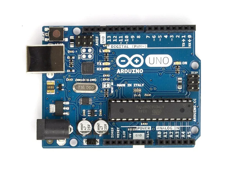 Arduino Uno R3In the simulator× 1See the price in the shop
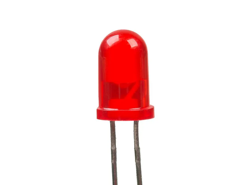 LED module 5 mm, redIn the simulator× 1See the price in the shop
delay() is easy to use, but it stops the whole sketch. A robot that waits cannot look. The fix is to check the clock instead of waiting. Three tools make this work: millis() timers, flags and a state machine.
What delay() really does
During delay(1000), the Uno runs no other line of your sketch for one second. It cannot read the sensor, change a motor or print a message. Only background work, such as counting time, goes on.
For a simple job, that is fine. The First drive sketch uses delay(STRAIGHT_MS), 1200 ms, for each side of its square. That robot has no sensor and nothing else to do. Now imagine a distance sensor on it. For 1.2 seconds on each side, the robot would not look. It would hit a wall that appears in that time.
delay() also makes two jobs at once hard. Try to blink one LED every 500 ms and another every 170 ms with delay(). Every delay() holds up both LEDs. You would have to work out a combined timetable by hand. And it would break as soon as you add a third job.
Some functions wait a little by themselves. In our robot sketches, pulseIn() waits up to 25 ms for an echo. Such short waits are acceptable. The problem is a long wait at a time when the robot should be looking.
millis(): a clock you can read
millis() returns the number of milliseconds since the board started. It counts up by itself, in the background, while your sketch runs. It returns an unsigned long: a whole number from 0 to 4,294,967,295. Keep every time value in an unsigned long variable too. An int is not enough: on the Uno it holds numbers only up to 32,767. As milliseconds, that is less than 33 seconds.
Think of cooking rice. You do not stand at the pot for 20 minutes. You note the time when you start. Then you look at the clock from time to time: have 20 minutes passed? In between, you do other things. A millis() timer works the same way.
The timer pattern
Here is one of the two timers from the TwoTimers sketch:
unsigned long now = millis();

if (now - moduleTimer >= MODULE_MS) {
  moduleTimer = now;
  moduleOn = !moduleOn;
  digitalWrite(LED_MODULE, moduleOn);
}
now - moduleTimeris the time since the LED last changed.>= MODULE_MSasks: have at least 500 ms passed?- If yes, the sketch saves the new time in
moduleTimer, flips the flag and sets the pin. - If no, it skips the block. It does not wait. It goes on to the next job and asks again on the next pass of
loop().
Use >=, not ==. The sketch may be busy with something else at exactly 500 ms, for example inside pulseIn(). With >=, the timer still fires, a little late. With ==, it can miss its moment and never fire.
Why subtraction survives the wrap
After 4,294,967,295 ms, about 49.7 days, millis() starts again from 0. This is called a wrap, or overflow.
Unsigned numbers count like a clock face. On a 12-hour clock, from 11 o'clock to 2 o'clock is 3 hours, even though 2 is smaller than 11. Subtraction with unsigned long works the same way. It always gives the time that passed, counted forwards.
An example with real numbers:
moduleTimeris 4,294,967,000: that is 296 ms before the wrap.nowis 204: that is 204 ms after the wrap.- The real time that passed is 296 + 204 = 500 ms.
- The Uno computes 204 - 4,294,967,000 in
unsigned longand gets exactly 500. The timer fires on time.
The other way of writing it, now >= moduleTimer + MODULE_MS, fails here. The sum 4,294,967,000 + 500 wraps round to 204. Just after the timer was set, now is still about 4,294,967,000. That is more than 204, so the check is true immediately, on every pass, until millis() wraps.
A robot rarely runs for 49 days. But the correct pattern is no harder to write, and some devices, such as a greenhouse controller, run for months.
Two LEDs, two timers
// Two timers: two LEDs blink at different speeds, and loop() never waits.
// Wiring: LED module S -> D2, - -> GND. The Uno's own L LED is on D13.

const byte LED_MODULE = 2;
const byte LED_BOARD = 13;

const unsigned long MODULE_MS = 500;   // the module toggles every 500 ms
const unsigned long BOARD_MS = 170;    // the L LED every 170 ms

unsigned long moduleTimer = 0;
unsigned long boardTimer = 0;
bool moduleOn = false;
bool boardOn = false;

void setup() {
  pinMode(LED_MODULE, OUTPUT);
  pinMode(LED_BOARD, OUTPUT);
}

void loop() {
  unsigned long now = millis();

  // "Has enough time passed?" Subtracting stays right even when millis() wraps round after 49.7 days.
  if (now - moduleTimer >= MODULE_MS) {
    moduleTimer = now;
    moduleOn = !moduleOn;
    digitalWrite(LED_MODULE, moduleOn);
  }

  if (now - boardTimer >= BOARD_MS) {
    boardTimer = now;
    boardOn = !boardOn;
    digitalWrite(LED_BOARD, boardOn);
  }

  // Anything else can run here, because nothing above ever waits.
}
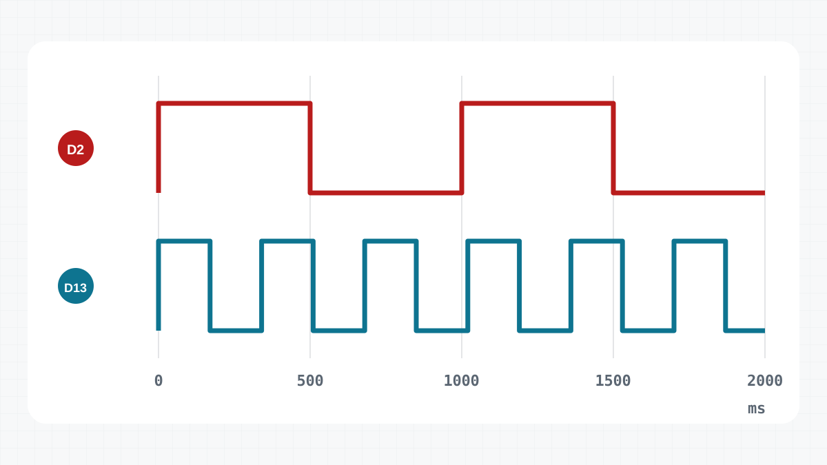
TwoTimers gives each LED its own timer: a variable that holds the time of the last change, and a constant interval.
| LED | Pin | Changes every | One full blink |
|---|---|---|---|
| LED module | D2 | 500 ms (MODULE_MS) | 1 s: once a second |
| L LED on the Uno | D13 | 170 ms (BOARD_MS) | 340 ms: almost three times a second |
loop() runs many thousands of times a second. On most passes, both checks say "not yet", and nothing happens. Sometimes one of them fires, changes its LED and saves the time. Neither timer waits for the other.
The wiring is the same as in the Blink project: the LED module's S pin on D2 and its - pin on GND.
Note where the variables live. moduleTimer, boardTimer, moduleOn and boardOn are declared at the top, outside loop(). A variable declared inside loop() is created again on every pass and forgets its value.
Flags: remembering yes or no
moduleOn and boardOn are flags: bool variables that remember a yes-or-no fact. moduleOn = !moduleOn flips the flag: true becomes false, and false becomes true. digitalWrite(LED_MODULE, moduleOn) then sets the pin HIGH for true and LOW for false.
Flags are good for simple facts: is the LED on, has the robot started? For a robot with several modes, many flags get confusing. Nothing stops two of them from being true at once, even when that makes no sense. For modes, use a state machine.
What you will see in the simulator
Build the desk robot of the Blink project in the simulator: the Uno and the LED module, with S on D2. Paste the TwoTimers sketch above into Code and press Upload. On the desk, the Uno runs from the laptop's USB. The LED module blinks once a second, and the L LED blinks almost three times a second. Because 500 is not a multiple of 170, the two LEDs change at different moments, and the pattern between them keeps shifting. Neither LED ever waits for the other.
A state machine: one variable for what the robot does
The obstacle avoider has three jobs that follow each other: drive ahead, drive backwards, turn. Each job is a state. The robot is always in exactly one state.
enum class State : byte { Drive, Back, Turn };
State state = State::Drive;
enum class makes a new type with three named values. : byte stores it in one byte of RAM. The variable state holds the current state. Why not plain numbers? With an int, state = 2 would mean nothing to a reader, but state = State::Turn does. enum class is also strict: the compiler does not accept a plain number as a State. And the names stay inside State, so they cannot mix with other names in the sketch.
In loop(), switch (state) jumps to the case of the current state. Each case does two things. It sets the motors, and it checks whether it is time to change state. break ends the case.
The function enter(next) changes the state. It also saves the time in stateStart, so each state can time itself. When the next state is Drive, it sets lastPing to 0. This makes the robot measure again immediately, instead of driving on with an old distance.
Measuring is not a state. It has its own timer at the top of loop(): every 60 ms, in every state. That is why the robot keeps measuring while it drives backwards and turns.
// Obstacle avoider: drive ahead; when something is close, back off and turn.
// Written without delay() in loop(): a state machine and millis() timers,
// so the robot keeps measuring while it moves.
// L298N: ENA -> D5, IN1 -> D4, IN2 -> D7 (left), ENB -> D6, IN3 -> D8, IN4 -> D12 (right)
// HC-SR04: TRIG -> D9, ECHO -> D10

const byte ENA = 5, IN1 = 4, IN2 = 7;
const byte ENB = 6, IN3 = 8, IN4 = 12;
const byte TRIG = 9, ECHO = 10;

const int CRUISE = 190;               // forward speed, 0..255
const int STOP_CM = 25;               // closer than this: avoid it
const unsigned long PING_MS = 60;     // the HC-SR04 needs a pause between pings
const unsigned long BACK_MS = 300;
const unsigned long TURN_MS = 380;

enum class State : byte { Drive, Back, Turn };
State state = State::Drive;
unsigned long stateStart = 0;
unsigned long lastPing = 0;
int distanceCm = 400;

void setMotor(byte enablePin, byte inA, byte inB, int speed) {
  speed = constrain(speed, -255, 255);
  digitalWrite(inA, speed > 0);
  digitalWrite(inB, speed < 0);
  analogWrite(enablePin, abs(speed));
}

void drive(int left, int right) {
  setMotor(ENA, IN1, IN2, left);
  setMotor(ENB, IN3, IN4, right);
}

// Distance in centimetres; 400 when no echo came back (nothing within about 4 m).
int readDistanceCm() {
  digitalWrite(TRIG, LOW);
  delayMicroseconds(2);
  digitalWrite(TRIG, HIGH);            // a 10 microsecond pulse starts a measurement
  delayMicroseconds(10);
  digitalWrite(TRIG, LOW);
  unsigned long us = pulseIn(ECHO, HIGH, 25000UL);  // wait at most 25 ms
  if (us == 0) return 400;
  return us / 58;                      // sound goes there and back: 58 us per cm
}

void enter(State next) {
  state = next;
  stateStart = millis();
  if (next == State::Drive) lastPing = 0;  // measure again before driving on
}

void setup() {
  const byte pins[] = {ENA, IN1, IN2, ENB, IN3, IN4, TRIG};
  for (byte pin : pins) pinMode(pin, OUTPUT);
  pinMode(ECHO, INPUT);
  Serial.begin(9600);
}

void loop() {
  unsigned long now = millis();
  if (now - lastPing >= PING_MS) {
    lastPing = now;
    distanceCm = readDistanceCm();
    Serial.println(distanceCm);
  }

  switch (state) {
    case State::Drive:
      drive(CRUISE, CRUISE);
      if (distanceCm < STOP_CM) enter(State::Back);
      break;
    case State::Back:
      drive(-160, -160);
      if (now - stateStart >= BACK_MS) enter(State::Turn);
      break;
    case State::Turn:
      drive(170, -170);                // spin right on the spot
      if (now - stateStart >= TURN_MS) enter(State::Drive);
      break;
  }
}Draw the state diagram as a table
On paper, you can draw each state as a circle and each change as an arrow. A table holds the same information and is easier to type:
| State | What the robot does | When it changes | Next state |
|---|---|---|---|
| Drive | drive(CRUISE, CRUISE): forwards at 190 |
the distance is below STOP_CM (25 cm) | Back |
| Back | drive(-160, -160): backwards at 160 |
BACK_MS (300 ms) after entering Back | Turn |
| Turn | drive(170, -170): spins right on the spot |
TURN_MS (380 ms) after entering Turn | Drive |
To plan your own robot, fill in such a table first, one row per state. Then write one case for each row. The "When it changes" column becomes the if, and the "Next state" column becomes the call to enter().
A new behaviour is a new row. For example, a Stop state could hold the robot still while something is closer than 10 cm, and go back to Drive when the way is clear. You add one row for Stop and one new condition in the Drive row. The rest stays the same.
Run the obstacle avoider in an arena and watch the Serial Monitor. The distances keep coming, about every 60 ms, also while the robot drives backwards and turns. With delay() in those states, the numbers would stop. The whole robot is in the Obstacle avoider project.
Check yourself
1Why is delay() a problem for a robot with a sensor?
During delay(), no other line of the sketch runs. The robot cannot measure or react until the delay ends.
2Why is now - timer >= interval safe when millis() wraps back to 0?
Subtraction with unsigned long counts round like a clock face, so the result is still the real time that has passed.
3In the obstacle avoider, what makes the robot leave the Turn state?
Time: when 380 ms (TURN_MS) have passed since it entered Turn, enter(State::Drive) sends it back to Drive.
Task
Change TwoTimers so that the LED module gives a short flash once a second: on for 100 ms, then off for 900 ms. The L LED must keep changing every 170 ms, as before. Upload the sketch on the desk and check that both LEDs still run at the same time.
Hint
The time to wait can depend on whether the LED is on or off right now.