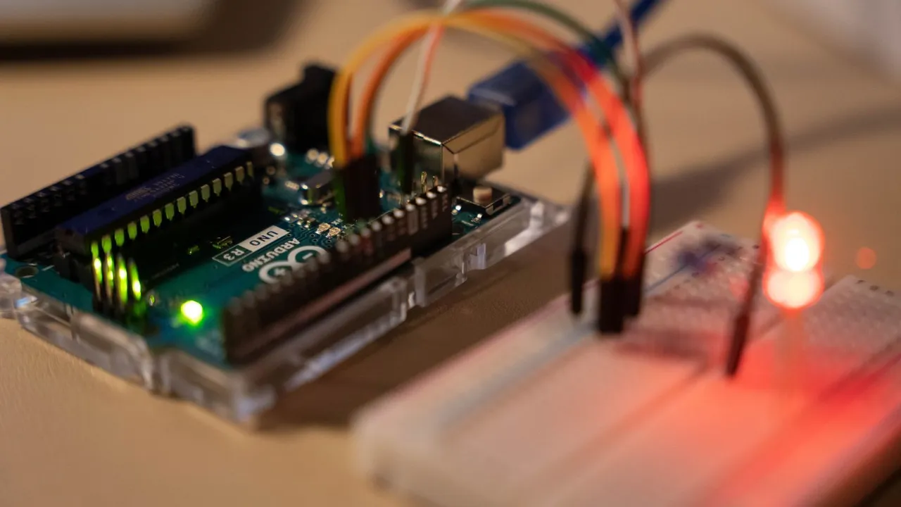
Blink is the classic first sketch. Two LEDs take turns: a red LED module on pin D2 and the small L LED that is built into the Uno on pin D13. While one is on, the other is off, and every half second they swap. You will learn how a sketch is built, how the Uno switches its pins, and how to wire a module and upload code. It is a beginner project and takes about 15 minutes.
What you need
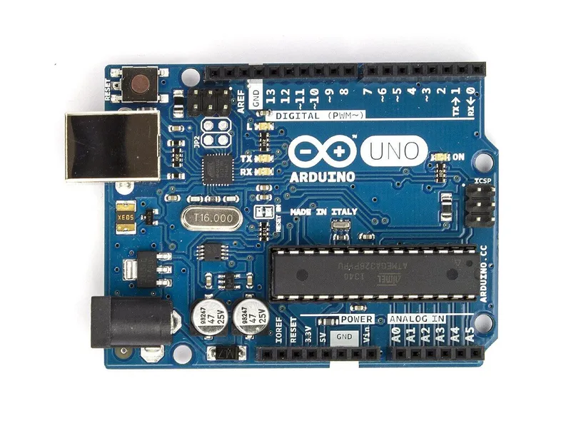 Arduino Uno R3In the simulator× 1See the price in the shop
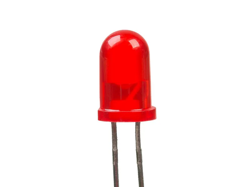 LED module 5 mm, redIn the simulator× 1See the price in the shop
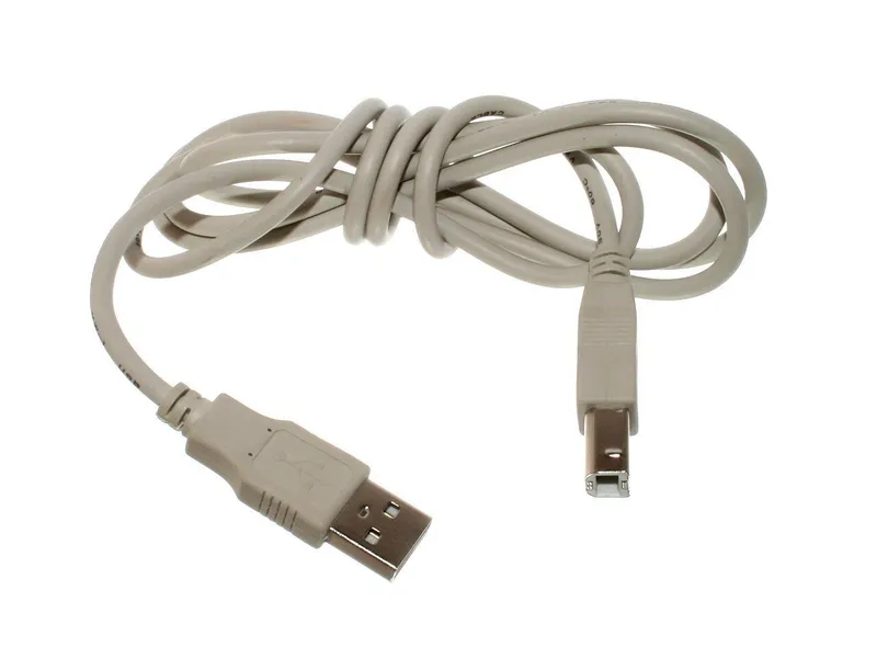 USB A–B cable for Arduino Uno× 1See the price in the shop
In the simulator, that is all. On the simulator's desk the Uno gets its power from the laptop's USB port, just like a real Uno that is plugged into a computer. For the real build you also need a computer with the Arduino IDE, which is free from arduino.cc. See also the starter kit in the Market.
How it works
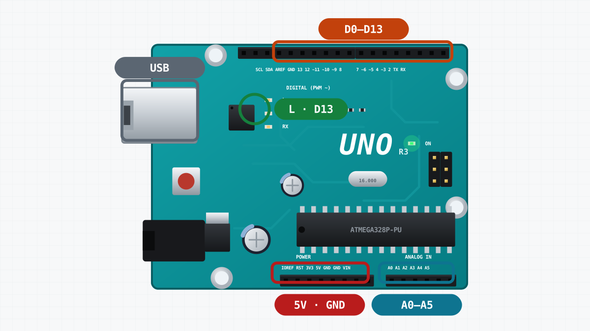
Each digital pin of the Uno works like a switch that your sketch controls. When the sketch sets a pin HIGH, the pin gives 5 V. When it sets the pin LOW, the pin gives 0 V, the same as GND.
The LED module is a small board with a red LED and a 220 ohm resistor. When D2 is HIGH, current flows from D2 through the resistor and the LED, out of the module's - pin, and back to the Uno's GND. This closed path is a circuit. Without the GND wire there is no path, and the LED stays dark.
The resistor limits the current. A red LED uses about 2 V, so about 3 V is left across the resistor. 3 V divided by 220 ohm is about 14 mA. That is well below the 20 mA that an Uno pin can give safely.
The L LED is already on the Uno board and connected to D13, so it needs no wires at all.
Here is what the two pins do during one second:
| Time | D2: LED module | D13: L LED |
|---|---|---|
| 0 to 500 ms | HIGH: on | LOW: off |
| 500 to 1000 ms | LOW: off | HIGH: on |
| After 1000 ms | the same again | the same again |
The pattern repeats for as long as the Uno has power.
Build it
1. Build it in the simulator
This project needs no body: the Uno and the LED module stand side by side on the desk, and the Uno runs from the laptop's USB.
Real build: put the Uno on a table with nothing metal under it. Metal can connect the pins on the bottom of the board to each other.
2. Wire the LED module
| From | To | Why |
|---|---|---|
| Uno GND | LED module GND | Ground |
| Uno D2 | LED module S | HIGH lights the LED |
Two wires are enough: S goes to D2, and - goes to GND. The Uno has several GND pins. They are all connected inside the board, so any of them works.
Real build: most LED modules have pins, and the Uno has sockets. So use jumper wires with a pin on one end and a socket on the other (male-to-female). Connect the wires before you plug in the USB cable. Changing wires on a board that has power can cause a short circuit.
3. Verify the sketch
Open Code. It works like the Arduino IDE. Paste the Blink sketch from this page (the Copy button above the code copies it) and press Verify. The sketch is compiled: it is turned from C++ text into machine code for the ATmega328P, the chip on the Uno. The simulator uses the same compiler tools as the real Arduino IDE. If there is a mistake, an error message shows the line where it is.
Real build: start the Arduino IDE, create a new sketch and paste the code from this page. The Copy button above the code copies it for you. Choose the board "Arduino Uno" and press Verify.
4. Upload and watch
Press Upload. The sketch goes to the Uno and starts at once. The LED module and the L LED now take turns every half second.
Real build: connect the Uno to the computer with the USB cable. The Uno R3 has a square USB-B socket, the same kind that printers use. In the IDE, choose the port where the Uno appears and press Upload. The small TX and RX LEDs on the board flicker while the sketch is sent, and then the blinking starts. The sketch stays in the Uno's memory, even without power. The next time the Uno gets power, the sketch starts again by itself.
5. Change it
Change both delay(500) lines to delay(100) and upload again. The LEDs now swap five times faster. Then move the S wire from D2 to D3, and change LED_MODULE from 2 to 3. The wire and the number in the sketch must always match. When they do not, the LED stays dark.
The code
// Blink: the LED module on D2 and the Uno's own "L" LED on D13 take turns.
// Wiring: LED module S -> D2, LED module - (GND) -> GND.

const byte LED_MODULE = 2;   // the module's S pin
const byte LED_BOARD = 13;   // the L LED soldered on the Uno

void setup() {
  pinMode(LED_MODULE, OUTPUT);  // pins start as inputs: make these two outputs
  pinMode(LED_BOARD, OUTPUT);
}

void loop() {
  digitalWrite(LED_MODULE, HIGH);  // 5 V on D2: the module's LED lights
  digitalWrite(LED_BOARD, LOW);    // 0 V on D13: the L LED goes dark
  delay(500);                      // wait half a second
  digitalWrite(LED_MODULE, LOW);
  digitalWrite(LED_BOARD, HIGH);
  delay(500);
}Names for the pins
const byte LED_MODULE = 2;   // the module's S pin
const byte LED_BOARD = 13;   // the L LED soldered on the Uno
These two lines give names to pin numbers. const means that the value never changes while the sketch runs. byte is a whole number from 0 to 255, which is enough for a pin number. The rest of the sketch uses the names. So when you move a wire, you change one number here and nothing else.
setup(): runs once
setup() runs one time, when the Uno starts. All pins start as inputs, which can only listen. pinMode(LED_MODULE, OUTPUT) turns D2 into an output that can give 5 V or 0 V. The next line does the same for D13.
loop(): runs forever
After setup(), the Uno runs loop() again and again, for as long as it has power. Here is its first half:
  digitalWrite(LED_MODULE, HIGH);  // 5 V on D2: the module's LED lights
  digitalWrite(LED_BOARD, LOW);    // 0 V on D13: the L LED goes dark
  delay(500);                      // wait half a second
digitalWrite() sets a pin HIGH (5 V) or LOW (0 V). delay(500) makes the Uno wait 500 milliseconds. A millisecond is one thousandth of a second. The second half of loop() does the opposite: D2 LOW, D13 HIGH, and another 500 ms. Then loop() starts again from the top.
What delay() costs
While delay() waits, the Uno does nothing else. For Blink that is fine. A robot, however, must drive, measure and decide at the same time, and it cannot stop to wait. The lesson on millis() and states shows how to blink without delay().
If it does not work
- Nothing blinks in the simulator. Press Upload, not only Verify. Verify only compiles the sketch. Upload sends it to the board.
- An error appears when you verify. Look at the line number in the message. A missing
;or a wrong capital letter is a common cause:digitalwriteis not the same asdigitalWrite. To start again, copy the original sketch with the Copy button. - The L LED blinks, but the module stays dark. Check that S goes to D2 and - goes to GND. If the two wires are swapped, current cannot flow through the LED in that direction, so it does not light. Also check that
LED_MODULEmatches the pin you used. - The module's LED glows very weakly. The pin is still an input. Check that
setup()haspinMode(LED_MODULE, OUTPUT). - The IDE does not show the Uno's port (real build). Unplug the cable and plug it in again, then look at which port appears. Try another USB cable, because some cables carry power only. Some Uno copies use a CH340 USB chip, which needs a driver on some computers.
- The upload fails with a message that the programmer is not responding (real build). Check that the board is set to Arduino Uno and that the right port is chosen. Remove any wires from D0 and D1: these pins carry the USB data.
Next steps
You can now switch a pin from a sketch. This is also how a robot controls its lights and its motor driver.
- Get to know the board better in the lesson on the Arduino Uno and its first program.
- Blink two LEDs at two different speeds, without
delay(), in the lesson on millis() and states. - Make something move: First drive builds the robot car and drives a square.
Make it better
- Make a short flash: the LED module on for 100 ms, then off for 900 ms.
- Make both LEDs blink together instead of taking turns.
- Blink SOS in Morse code: three short flashes, three long flashes, three short flashes.