Arduino Uno: pins and your first program
The Arduino Uno's pins and power, HIGH and LOW, why an LED needs a resistor, and your first sketch: two LEDs that take turns, from setup() and loop() to Upload.
Key points
- Digital pins D0-D13 work as outputs or inputs; HIGH is about 5 V and LOW is 0 V.
- PWM pins are marked ~ (D3, D5, D6, D9, D10, D11); A0-A5 are analog inputs.
- A pin gives 20 mA safely and 40 mA at most, so an LED always needs a resistor.
- setup() runs once, and then loop() runs again and again.
- Verify compiles and checks the sketch; Upload also writes it into the board.
The Arduino Uno is a small board built around one chip: the ATmega328P microcontroller. The rest of the board serves that chip. It brings power, connects the chip to your computer, and leads the chip's pins to the rows of sockets along the edges. Those sockets are where you plug in wires.
The board at a glance
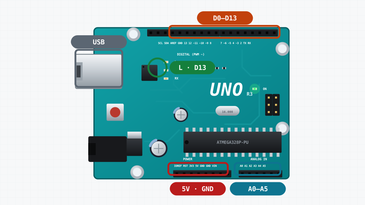
| Part of the board | What it is for |
|---|---|
| USB socket | Connects the board to a computer. It gives the board about 5 V (up to 500 mA) and carries uploads and Serial messages. |
| Round power socket | Takes 7-12 V from a battery or an adapter. The board's regulator turns it into 5 V. |
| ATmega328P | The microcontroller: 16 MHz, 32 KB flash memory for the sketch, 2 KB RAM, 1 KB EEPROM. |
| Digital pins D0-D13 | Outputs or inputs for on/off signals. D0 and D1 also carry the USB serial link. |
| PWM pins, marked ~ | D3, D5, D6, D9, D10 and D11 can also switch on and off very fast, to set a speed or a brightness. |
| Analog inputs A0-A5 | Measure a voltage from 0 to 5 V as a number from 0 to 1023. |
| Power pins | 5V, 3.3V, GND and VIN (see below). |
| L LED | A small LED connected to D13. Your first sketch uses it. |
| ON LED | Lights when the board has power. |
| TX and RX LEDs | Flicker when data goes to or from the computer. |
| Reset button | Starts your sketch again from the beginning. |
Power pins
- 5V gives 5 V to sensors and modules. On the robot car, power comes in through this pin instead: the L298N motor driver feeds the Uno here. The 5V pin has no protection, so never put more than 5 V on it.
- 3.3V gives 3.3 V for small parts that need it, up to about 50 mA. The robot car does not use it.
- GND is ground, 0 V. Every voltage on the board is measured from GND. The Uno has three GND pins, and they are connected together on the board.
- VIN takes 7-12 V, like the round power socket. The board's own regulator makes 5 V from it.
HIGH and LOW
A digital pin used as an output has two states. HIGH connects the pin to the board's supply: about 5 V when the Uno runs from USB. LOW connects it to GND: 0 V. There is nothing in between. digitalWrite(2, HIGH) puts about 5 V on D2, and digitalWrite(2, LOW) puts 0 V on it.
A pin used as an input does the opposite job. digitalRead(pin) tells your sketch whether the voltage on the pin is high or low. After a reset, every pin is an input. Before a pin can drive anything, the sketch must make it an output with pinMode(pin, OUTPUT).
PWM and analog pins, in short
The ~ pins can switch between HIGH and LOW very fast: about 980 times a second on D5 and D6, and about 490 times a second on the others. analogWrite(pin, value) sets the share of time the pin is HIGH. The value goes from 0 to 255: 0 means always LOW, 255 always HIGH, and 128 about half the time. The lesson Motors and the L298N driver uses this to set a motor's speed.
The analog inputs A0-A5 measure a voltage. analogRead(A0) returns 0 for 0 V, 1023 for 5 V, and the steps in between.
How much current a pin can give
A pin gives about 20 mA safely. The absolute maximum is 40 mA. Above that, the pin can be damaged for good. 20 mA is enough for an LED. It is far too little for a motor, which needs up to 1 A. That is why motors need a driver.
Why an LED needs a resistor
An LED does not limit its own current. A red LED needs about 2 V to light. Above that, a little more voltage makes the current rise very steeply, until the LED or the pin burns. A resistor in series with the LED prevents this.
The LED module used on this site has its own 220 Ω (ohm) resistor. Here is the current it allows:
- The pin gives 5 V, and the red LED takes about 2 V.
- About 3 V is left for the resistor.
- Current = 3 V / 220 Ω ≈ 0.014 A = 14 mA.
14 mA makes the LED bright, and it is safely below the pin's 20 mA.
Wiring the LED module
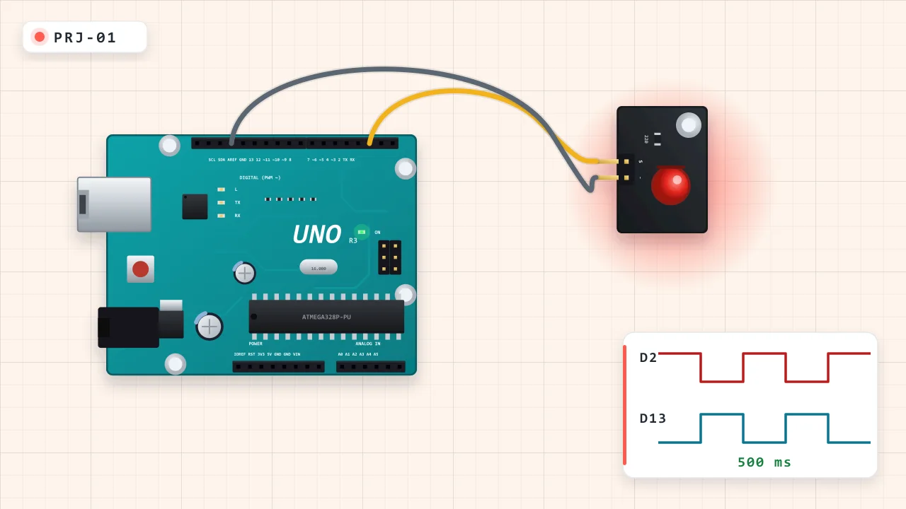
The LED module has two pins: S (signal) and - (minus, ground). Connect S to D2 and - to a GND pin of the Uno. The L LED on D13 is part of the board, so it needs no wire.
| From | To | Why |
|---|---|---|
| Uno GND | LED module GND | Ground |
| Uno D2 | LED module S | HIGH lights the LED |
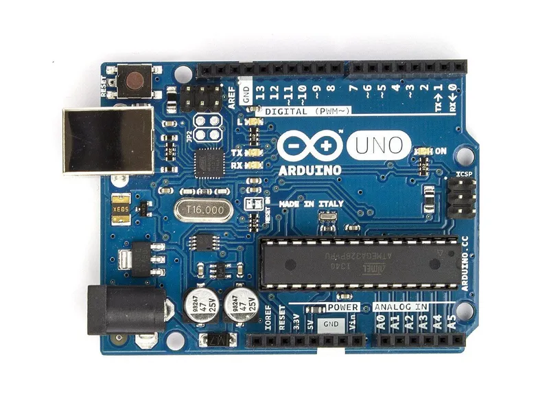 Arduino Uno R3In the simulator× 1See the price in the shop
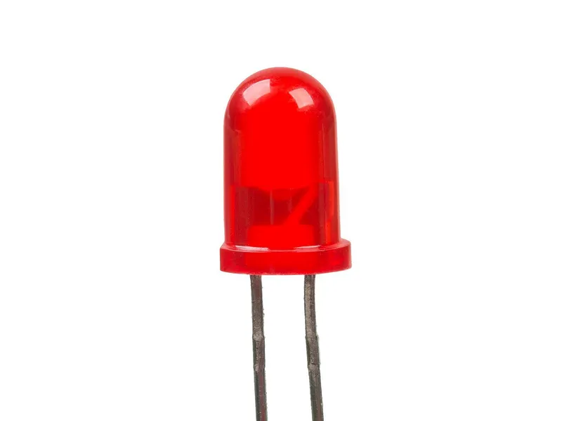 LED module 5 mm, redIn the simulator× 1See the price in the shop
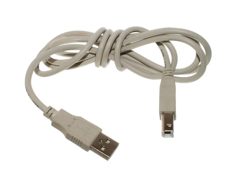 USB A–B cable for Arduino Uno× 1See the price in the shop
The sketch
// Blink: the LED module on D2 and the Uno's own "L" LED on D13 take turns.
// Wiring: LED module S -> D2, LED module - (GND) -> GND.

const byte LED_MODULE = 2;   // the module's S pin
const byte LED_BOARD = 13;   // the L LED soldered on the Uno

void setup() {
  pinMode(LED_MODULE, OUTPUT);  // pins start as inputs: make these two outputs
  pinMode(LED_BOARD, OUTPUT);
}

void loop() {
  digitalWrite(LED_MODULE, HIGH);  // 5 V on D2: the module's LED lights
  digitalWrite(LED_BOARD, LOW);    // 0 V on D13: the L LED goes dark
  delay(500);                      // wait half a second
  digitalWrite(LED_MODULE, LOW);
  digitalWrite(LED_BOARD, HIGH);
  delay(500);
}Names for pins
const byte LED_MODULE = 2; gives pin 2 a name. byte is a whole number from 0 to 255, and const means the value never changes. Names make the sketch easier to read. If you move a wire, you change one number at the top, and the rest of the sketch stays the same.
setup() runs once
When the board starts, after power-on, a reset or an upload, it runs setup() one time. Here, setup() makes D2 and D13 outputs.
loop() runs forever
After setup(), the board runs loop(). When loop() reaches its end, it starts again from the top, for as long as the board has power. One pass of this loop() has two halves:
- D2 HIGH and D13 LOW: the module's LED lights and the L LED goes dark. Then the sketch waits 500 ms.
- D2 LOW and D13 HIGH: the module goes dark and the L LED lights. Then the sketch waits another 500 ms.
One pass takes one second. So each LED lights once a second, and the two always take turns.
The three functions
| Function | What it does | Example from the sketch |
|---|---|---|
pinMode(pin, mode) |
Makes a pin an OUTPUT or an INPUT | pinMode(LED_MODULE, OUTPUT); |
digitalWrite(pin, value) |
Puts HIGH (about 5 V) or LOW (0 V) on an output pin | digitalWrite(LED_MODULE, HIGH); |
delay(ms) |
Waits that many milliseconds | delay(500); |
During a delay(), the Uno runs no other line of your sketch. For Blink, that is fine. A robot that must watch its sensor all the time needs another way to keep time: see Programs that never wait.
Verify and Upload
The Arduino IDE has two main buttons:
- Verify (the check mark, Ctrl+R) compiles the sketch. It turns your C++ into machine code and checks it. If there is a mistake, such as a missing semicolon, it shows an error with the line number.
- Upload (the arrow, Ctrl+U) compiles the sketch and writes it into the board's flash memory. The board then restarts and runs the new sketch.
The simulator's built-in Arduino IDE has the same buttons and the same shortcuts.
A new Uno usually comes with a Blink sketch already on it, so its L LED blinks when you first plug it in. In the simulator, a board with no uploaded sketch runs this factory Blink too.
Try it in the simulator
Here the robot is just the Uno and the LED module, standing on the desk in the Garage. The Uno runs from the laptop's USB, so it needs no battery. After Upload, the red LED module and the L LED take turns: one lights while the other is dark, and they swap every half second. Now change both delay(500) lines to delay(100) and upload again. The LEDs swap five times faster.
Messages with Serial
The Uno can also send text to the computer over the USB cable. It is a simple way to see what your sketch is doing. Here is the Blink setup() with two added lines:
void setup() {
  pinMode(LED_MODULE, OUTPUT);
  pinMode(LED_BOARD, OUTPUT);
  Serial.begin(9600);              // open the link at 9600 baud
  Serial.println("Blink started"); // send one line of text
}
Serial.begin(9600) starts the serial link at 9600 baud (bits per second). Serial.println() sends text and ends the line. Serial.print() sends text without ending the line. On a real board, open Tools > Serial Monitor in the Arduino IDE and choose 9600 baud to read the messages. While Serial is on, D0 and D1 carry the messages, so keep other wires off these two pins.
In the simulator, the Serial Monitor is part of the arena, where the robot runs from its battery. The lesson Measuring distance with the HC-SR04 uses it to print distances.
Next
- Build the same circuit for real in the Blink project.
- Blink two LEDs at two different speeds, without
delay(), in Programs that never wait. - Make wheels turn in Motors and the L298N driver.
Check yourself
1What is the difference between setup() and loop()?
setup() runs once when the board starts. loop() then runs again and again, as long as the board has power.
2Why does the LED module have its own 220 ohm resistor?
An LED does not limit its own current. The resistor keeps the current at about 14 mA, which is safe for the LED and below the pin's 20 mA.
3Which Uno pins can make PWM with analogWrite()?
The pins marked with ~: D3, D5, D6, D9, D10 and D11.
Task
In the simulator, move the LED module's S wire from D2 to D8. Then change the sketch so that the module blinks again, upload it, and check the result on the desk.
Hint
The module's pin number is written in only one place in the sketch.