Motors and the L298N driver
Why a pin cannot drive a motor, how the L298N's H-bridge sets direction and speed, how to power the Uno from it safely, and what setMotor() does line by line.
Key points
- A pin gives 20 mA, but a TT motor needs about 0.3 A to drive and up to 1 A when stalled.
- An H-bridge reverses the current through a motor, so the motor can turn both ways.
- IN1 and IN2 set the direction; PWM on ENA, with its jumper removed, sets the speed from 0 to 255.
- The L298N loses about 1.8 V inside: from 6 V, the motors get about 4.2 V.
- The L298N's +5V feeds the Uno's 5V pin; join the grounds, and never put the battery on the 5V pin.
A motor needs much more current than an Arduino pin can give. The L298N motor driver sits between them. The Uno sends small signals, and the L298N switches the battery's power to the motors: on or off, forwards or backwards, fast or slow.
Why a pin cannot drive a motor
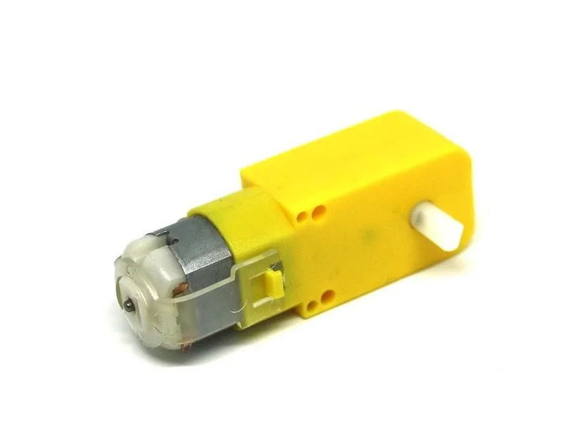
Photo: Lukas Ruge · CC0
Compare the numbers:
| What | Current |
|---|---|
| Uno pin, safe | 20 mA |
| Uno pin, absolute maximum | 40 mA |
| TT motor, turning freely | about 100-150 mA |
| TT motor, driving the robot | about 300 mA |
| TT motor, blocked (stalled) | up to about 1,000 mA (1 A) |
Even a free-running motor needs at least five times more current than a pin can safely give. A blocked wheel needs fifty times more.
There is a second problem. A motor is a coil of wire. When the current through a coil stops suddenly, the coil makes a short, high voltage spike. This spike can destroy a pin or a transistor. The L298N module has diodes that catch these spikes. So never connect a motor straight to an Arduino pin.
The H-bridge idea
To turn a DC motor the other way, you reverse the current through it. An H-bridge does this with four switches.
Picture the letter H. The motor is the bar in the middle. Each of the two upright lines has one switch above the motor and one switch below it. The tops connect to battery +, and the bottoms connect to GND.
- Close the top-left and the bottom-right switch. Current flows through the motor from left to right, and the motor turns one way.
- Close the top-right and the bottom-left switch. Current flows from right to left, and the motor turns the other way.
- Close both bottom switches. Now the motor's two wires are joined. A turning motor works as a generator, and this short circuit slows it down quickly: the motor brakes.
- Open all four switches. The motor is disconnected. It coasts until friction stops it.
Closing both switches on one side would connect battery + straight to GND. No combination of the inputs can do that. The L298N chip contains two H-bridges, so one module drives two motors. Its switches are transistors, so they can switch on and off very fast.
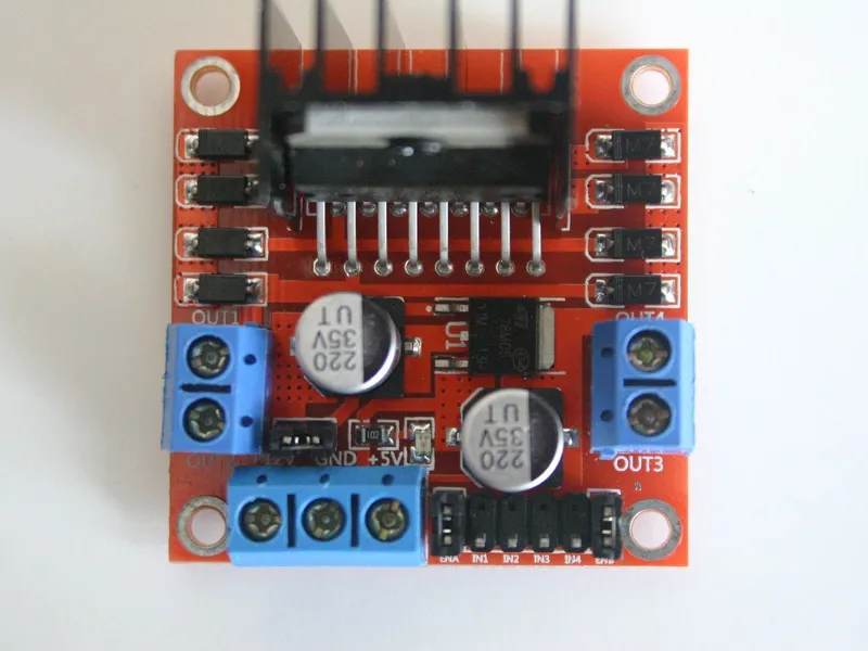
The L298N's terminals and pins
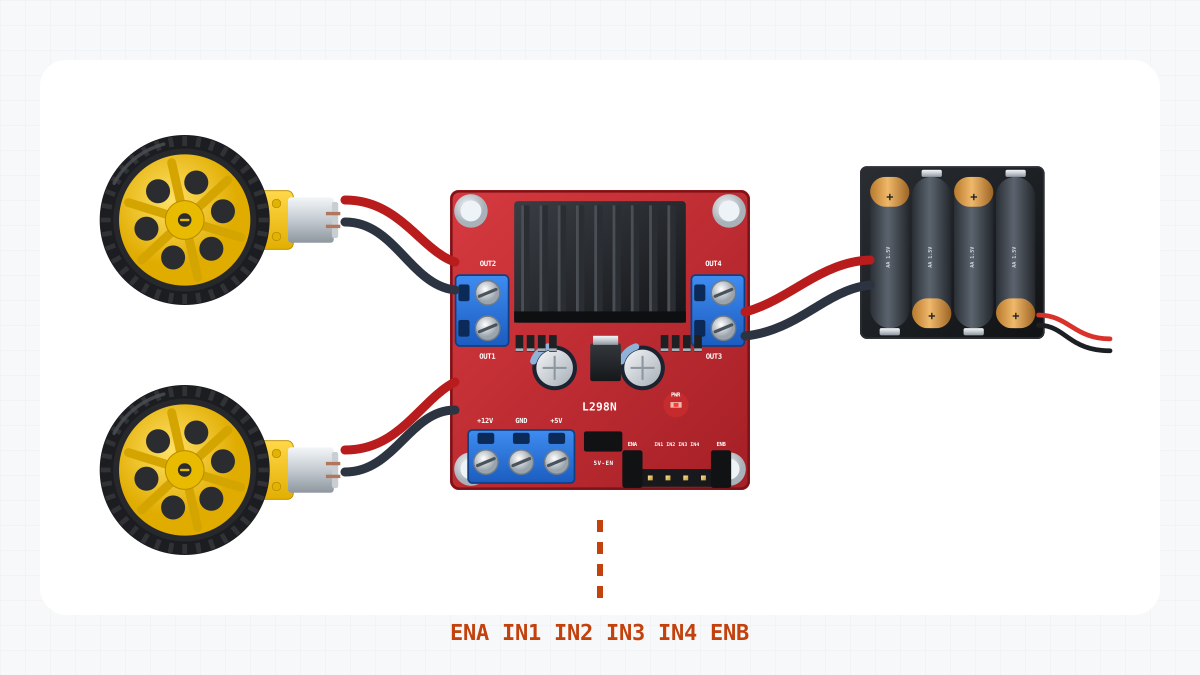
| Terminal or pin | What it is for | On the robot car |
|---|---|---|
| +12V | Motor supply, 5-35 V (the name is only a label) | Battery + (red), about 6 V |
| GND | Ground for the supply and for the signals | Battery - (black) and a GND pin of the Uno |
| +5V | Output of the module's own 5 V regulator, while its small regulator jumper (often marked 5V-EN) is on | The Uno's 5V pin, and the HC-SR04's VCC on robots that have one |
| OUT1, OUT2 | Motor A | Left motor |
| OUT3, OUT4 | Motor B | Right motor, leads swapped (see below) |
| ENA, ENB | Enable: on or off, and the speed, of motor A and motor B | D5 and D6 (PWM) |
| IN1, IN2 | Direction of motor A | D4 and D7 |
| IN3, IN4 | Direction of motor B | D8 and D12 |
Each channel can give up to 2 A, or about 1 A without extra cooling. A driving TT motor needs about 0.3 A.
A new module comes with small plugs, called jumpers, on ENA and ENB. A jumper connects the pin to 5 V. The motor is then always enabled: it runs at full speed whenever IN1 and IN2 differ. For speed control, remove both jumpers and wire ENA and ENB to PWM pins of the Uno. In the simulator, a wire from ENA to an Uno pin means that the jumper is off.
The truth table
For motor A:
| ENA | IN1 | IN2 | The motor |
|---|---|---|---|
| HIGH | HIGH | LOW | turns forwards |
| HIGH | LOW | HIGH | turns backwards |
| HIGH | HIGH | HIGH | brakes |
| HIGH | LOW | LOW | brakes |
| LOW | any | any | coasts (turns freely) |
Motor B works the same way with ENB, IN3 and IN4. "Forwards" here means the direction in which the motor turns when OUT1 is + and OUT2 is -. Which way the robot rolls also depends on how the motor is mounted.
Speed with PWM
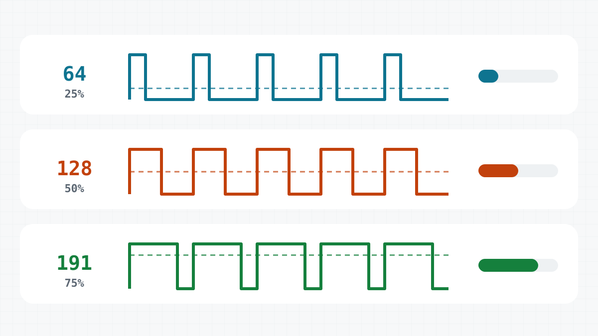
analogWrite(ENA, value) switches ENA on and off about 980 times a second. The value, from 0 to 255, sets the share of time the motor gets power. The motor and the wheel are too heavy to follow such fast pulses. They react to the average:
| analogWrite(ENA, ...) | Share of time on | Average voltage at the motor |
|---|---|---|
| 255 | 100 % | about 4.2 V |
| 200 | 78 % | about 3.3 V |
| 128 | 50 % | about 2.1 V |
| 0 | 0 % | none: the motor coasts |
At low values, the motor only hums and does not turn. The average voltage is too low to overcome the friction in the gearbox. Where this starts depends on the motor, the batteries and the floor. For this reason, the Keep distance sketch never drives slower than 90.
Where the volts go
The L298N uses bipolar transistors as switches. The motor current always flows through two of them: one at the top of the H and one at the bottom. Together they take about 1.8 V. So from a 6 V battery, the motors get only about 4.2 V. The simulator uses the same numbers.
TT motors are made for 3-6 V, so 4.2 V works. But the robot is slower than with the full 6 V.
How fast is the robot? One turn of a 65 mm wheel moves it π × 65 mm, about 20 cm. So a wheel that turns 150 times a minute drives the robot about 30 m a minute, or 0.5 m/s.
Powering the Uno from the L298N
The robot has only one battery. The L298N's own 5 V regulator also powers the Uno: its +5V terminal goes to the Uno's 5V pin.
The regulator needs about 7 V at its input to give a full 5 V. From four AA cells it gives about 4.4 V. That is a little low, but it is enough for the Uno to run.
Do not put the L298N's +5V on VIN either. VIN leads to the Uno's own regulator, which needs 7-12 V. With about 4.4 V at its input, the chip gets too little voltage to run. The simulator checks for both mistakes.
Common ground
A voltage is always measured between two points. When the Uno sets D4 HIGH, D4 is several volts above the Uno's GND. The L298N can only see this if it measures from the same GND. That is why the L298N's GND is wired to a GND pin of the Uno. On the robot car, this wire also carries the Uno's supply current back to the battery. If it is missing, the simulator reports that there is no common ground.
Why the right motor's leads are swapped
Both motors are the same, but the right one is mounted turned round, as a mirror image of the left one. With the same wiring, the same "forwards" signal would turn the right wheel backwards, and the robot would spin on the spot. So the right motor's leads are swapped on purpose: M+ goes to OUT4, and M- goes to OUT3. Now both wheels roll forwards for the same signal. The fix is in the wiring, so the code can treat both motors the same.
The wiring
Here is the full wiring of this page's robot.
| From | To | Why |
|---|---|---|
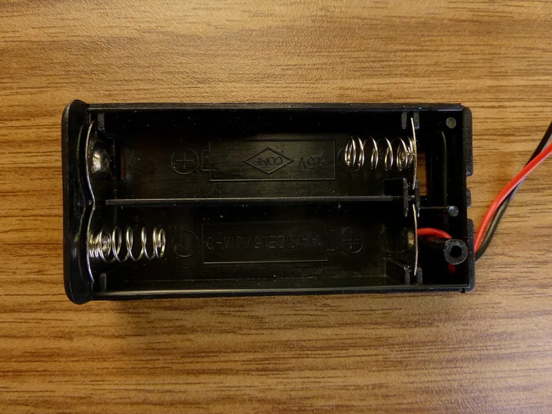
| Battery + | L298N +12V | Motor power: about 6 V from four AA cells |
| Battery - | L298N GND | The battery’s minus |
| L298N +5V | Uno 5V | The driver’s regulator powers the Uno: about 4.4 V |
| L298N GND | Uno GND | Common ground: the signals need the same 0 V |
| Uno D5 | L298N ENA | Left motor speed (PWM); the ENA jumper is removed |
| Uno D4 | L298N IN1 | Left motor direction |
| Uno D7 | L298N IN2 | Left motor direction |
| Uno D8 | L298N IN3 | Right motor direction |
| Uno D12 | L298N IN4 | Right motor direction |
| Uno D6 | L298N ENB | Right motor speed (PWM); the ENB jumper is removed |
| Left motor M+ | L298N OUT1 | |
| Left motor M- | L298N OUT2 | |
| Right motor M+ | L298N OUT4 | Swapped on purpose: this motor is mounted mirrored |
| Right motor M- | L298N OUT3 | Swapped on purpose: this motor is mounted mirrored |
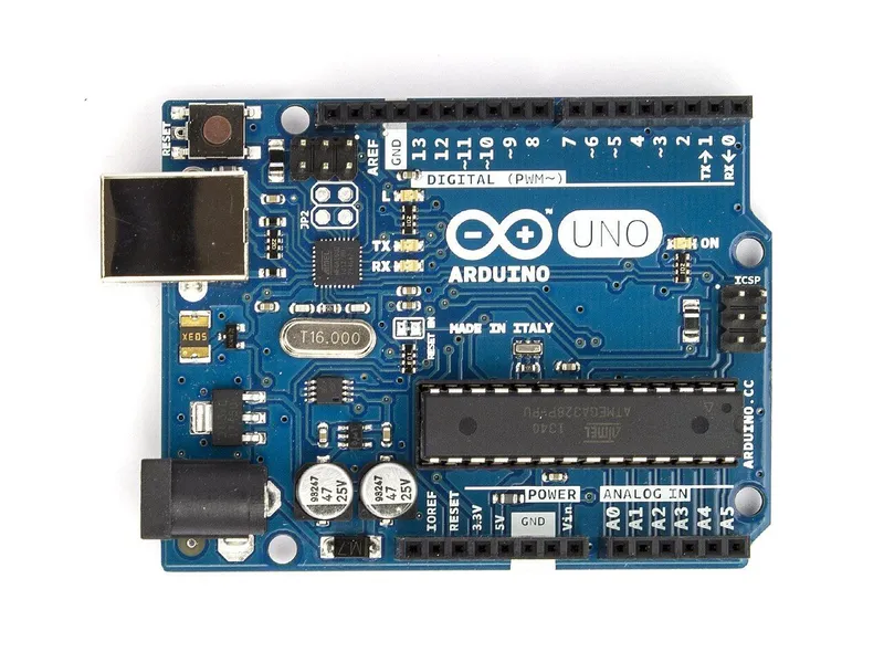 Arduino Uno R3In the simulator× 1See the price in the shop
 L298N motor driver moduleIn the simulator× 1See the price in the shop
- TT gear motor 1:48 with 65 mm wheelIn the simulator× 2See the price in the shop
 4 × AA battery holderIn the simulator× 1See the price in the shop
 Ball caster 20 mmIn the simulator× 1See the price in the shop
 Jumper wire set× 1See the price in the shop
The MotorTest sketch
// Motor test: both motors speed up, slow down, then the same backwards.
// L298N: ENA -> D5, IN1 -> D4, IN2 -> D7 (left), ENB -> D6, IN3 -> D8, IN4 -> D12 (right)

const byte ENA = 5, IN1 = 4, IN2 = 7;
const byte ENB = 6, IN3 = 8, IN4 = 12;

// speed from -255 (full backwards) to 255 (full forwards); 0 lets the motor coast
void setMotor(byte enablePin, byte inA, byte inB, int speed) {
  speed = constrain(speed, -255, 255);
  digitalWrite(inA, speed > 0);        // IN1 high, IN2 low: forwards
  digitalWrite(inB, speed < 0);        // IN1 low, IN2 high: backwards
  analogWrite(enablePin, abs(speed));  // PWM on ENA: how fast
}

void drive(int left, int right) {
  setMotor(ENA, IN1, IN2, left);
  setMotor(ENB, IN3, IN4, right);
}

void ramp(int direction) {
  for (int s = 0; s <= 255; s += 5) {
    drive(direction * s, direction * s);
    delay(30);
  }
  for (int s = 255; s >= 0; s -= 5) {
    drive(direction * s, direction * s);
    delay(30);
  }
}

void setup() {
  const byte pins[] = {ENA, IN1, IN2, ENB, IN3, IN4};
  for (byte pin : pins) pinMode(pin, OUTPUT);
}

void loop() {
  ramp(1);       // forwards
  delay(500);
  ramp(-1);      // backwards
  delay(500);
}
ramp(1) raises the speed of both motors from 0 to 255 in steps of 5, one step every 30 ms. Then it lowers the speed back to 0. That is 52 steps each way: about 1.6 seconds up and 1.6 seconds down. After a half-second pause, ramp(-1) does the same backwards. One full pass of loop() takes about 7 seconds. setup() makes the six control pins outputs with a short for loop over an array.
setMotor() line by line
Every sketch on this site that drives motors uses the same two functions. Here is the first one:
void setMotor(byte enablePin, byte inA, byte inB, int speed) {
  speed = constrain(speed, -255, 255);
  digitalWrite(inA, speed > 0);        // IN1 high, IN2 low: forwards
  digitalWrite(inB, speed < 0);        // IN1 low, IN2 high: backwards
  analogWrite(enablePin, abs(speed));  // PWM on ENA: how fast
}- Line 1. The function takes the three pins of one motor and a speed from -255 (full backwards) to 255 (full forwards).
- Line 2.
constrain()keeps the speed in that range. A speed of 300 becomes 255. - Line 3.
speed > 0is a comparison, so its result istrueorfalse.truecounts as HIGH, andfalseas LOW. So IN1 is HIGH only when the speed is positive. - Line 4. In the same way, IN2 is HIGH only when the speed is negative.
- Line 5.
abs()removes the minus sign: -160 becomes 160. This value goes to the PWM on ENA and sets how fast the motor turns.
Three examples for the left motor:
| Call | IN1 | IN2 | ENA | The motor |
|---|---|---|---|---|
setMotor(ENA, IN1, IN2, 200) |
HIGH | LOW | PWM 200 | forwards, fast |
setMotor(ENA, IN1, IN2, -160) |
LOW | HIGH | PWM 160 | backwards, slower |
setMotor(ENA, IN1, IN2, 0) |
LOW | LOW | always LOW | coasts |
Speed 0 lets the motor coast, because ENA is LOW. It does not brake.
The second function, drive(left, right), calls setMotor() twice: with ENA, IN1 and IN2 for the left motor, and with ENB, IN3 and IN4 for the right one. drive(200, 200) drives straight ahead, drive(-160, -160) drives backwards, and drive(170, -170) spins right on the spot.
Try it in the simulator
Start the robot in an arena. It moves forwards slowly, speeds up, slows down and stops. After half a second, it does the same backwards. The live motor readout rises and falls with each ramp. At the start of each ramp, the wheels do not turn yet, because the voltage is still too low.
Next, the First drive project uses the same drive() function to drive a square.
Check yourself
1Why can't an Arduino pin drive a TT motor directly?
A pin gives 20 mA safely, but the motor needs about 0.3 A while driving and up to 1 A when stalled. The voltage spike of a motor that is switched off could also damage the pin.
2ENA is HIGH, and IN1 and IN2 are both LOW. What does the motor do?
It brakes. Both motor wires are connected to GND, so the motor stops quickly.
3Why do the motors get only about 4.2 V from a 6 V battery?
The L298N's bipolar transistors lose about 1.8 V inside the bridge.
Task
In the simulator, wire the right motor the same way as the left one: M+ to OUT3 and M- to OUT4. Run MotorTest in an arena and watch what the robot does. Then make it drive straight again without touching the wires, by changing one line of the sketch.
Hint
Which way a motor turns depends only on which of its two IN pins is HIGH.