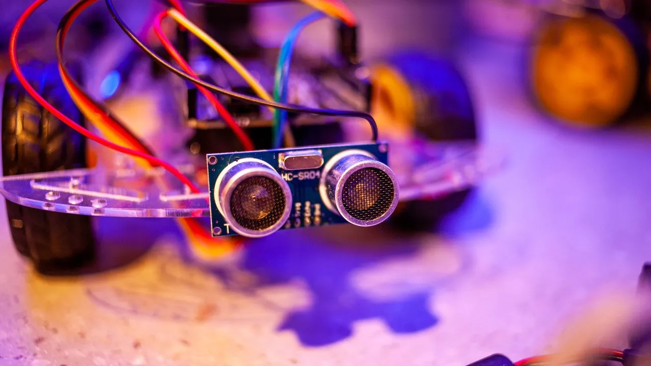
Hold a book in front of this robot, and it drives up to the book and stops 20 cm away. Move the book away, and the robot follows. Move it closer, and the robot drives backwards. The robot sets its speed from how far it is from 20 cm: fast when it is far away, slowly when it is nearly there. This is a proportional controller, or P controller. Machines use controllers like this to hold a speed, a temperature or a position. You will learn what error and gain mean, why the robot needs a minimum speed and a dead band, and how to tune the gain. It is an easy project and takes about 45 minutes.
What you need
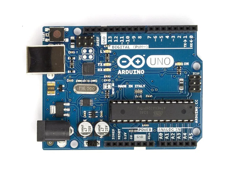 Arduino Uno R3In the simulator× 1See the price in the shop
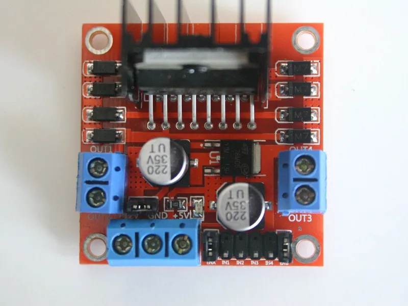 L298N motor driver moduleIn the simulator× 1See the price in the shop
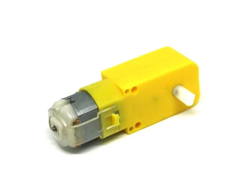 TT gear motor 1:48 with 65 mm wheelIn the simulator× 2See the price in the shop
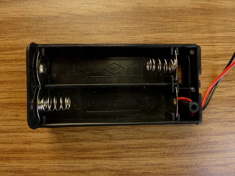 4 × AA battery holderIn the simulator× 1See the price in the shop
 Ball caster 20 mmIn the simulator× 1See the price in the shop
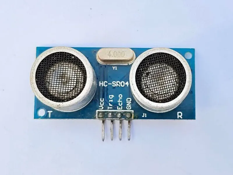 HC-SR04 ultrasonic sensorIn the simulator× 1See the price in the shop
 Jumper wire set× 1See the price in the shop
This is the same robot as the obstacle-avoiding robot: the car with an HC-SR04 at the front. Only the sketch is new. As a target, a book or a small box works better than a hand, because flat, hard surfaces send back a stronger echo.
How it works
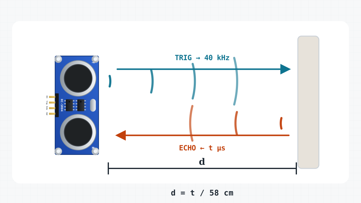
Error: how far from the target
The robot wants to be 20 cm from the object. This wanted distance is the target, TARGET_CM. After each measurement, the robot calculates the error:
error = distance - 20
At 30 cm the error is 10: the robot is too far away and must drive forwards. At 20 cm the error is 0: it is where it should be. At 15 cm the error is -5: it is too close and must drive backwards.
Gain: how hard to react
The speed is the error multiplied by the gain KP, which is 12 in this sketch:
speed = 12 × error
A big error gives a big speed, and a small error gives a small speed. So the robot hurries when it is far from the target and slows down as it gets close.
Three limits for real motors
- Top speed. The speed is kept between -255 and 255, the largest PWM value. From 42 cm to 150 cm, the robot drives at full speed.
- Minimum speed. Below about 90, the TT motors only hum and do not turn. So a small speed is raised to 90, or to -90 when the robot drives backwards.
- Dead band. When the error is 2 cm or less, so between 18 and 22 cm, the speed is 0. Without the dead band, the robot would twitch back and forth around 20 cm forever, because each reading differs a little and its smallest speed is 90.
One more rule: when nothing is within 150 cm, the robot waits. It does not chase a wall across the room.
| Distance | Error | 12 × error | Speed sent to the motors |
|---|---|---|---|
| 10 cm | -10 | -120 | -120: backwards |
| 17 cm | -3 | -36 | -90: raised to the minimum |
| 18 to 22 cm | -2 to 2 | 0: dead band, stand still | |
| 25 cm | 5 | 60 | 90: raised to the minimum |
| 30 cm | 10 | 120 | 120 |
| 40 cm | 20 | 240 | 240 |
| 60 cm | 40 | 480 | 255: the maximum |
| 200 cm | 0: nothing within 150 cm, wait |
What KP changes
- KP too small, for example 4: near the target, every result is below 90, so the robot creeps at the minimum speed. It is sluggish and falls behind a moving target.
- KP too big, for example 30: an error of 9 cm already gives full speed. The robot rushes, cannot stop in time, passes 20 cm and has to come back. It often rocks back and forth. This is called oscillation.
- KP about right: the robot moves quickly toward the target, slows down and stops near 20 cm without rocking.
Why does a big KP rock? The robot cannot stop at once: it keeps rolling for a moment, and the motors need time to slow down. In the dead band the motors coast, so the robot rolls on a little. Also, it corrects only about 20 times per second. With a big KP, the robot is already past the target before the next correction.
Build it
1. Get the robot in the simulator
The robot and its wiring are the same as for the obstacle-avoiding robot: if you built that one in the game, use it. If not, start from Obstacle avoider, the car that comes with the game, and make its wires match the table in step 2.
Real build: use your car from the obstacle-avoiding robot. Check that the HC-SR04 is level and looks straight ahead.
2. Check the wiring
| From | To | Why |
|---|---|---|
| Battery + | L298N +12V | Motor power: about 6 V from four AA cells |
| Battery - | L298N GND | The battery’s minus |
| L298N +5V | Uno 5V | The driver’s regulator powers the Uno: about 4.4 V |
| L298N GND | Uno GND | Common ground: the signals need the same 0 V |
| Uno D5 | L298N ENA | Left motor speed (PWM); the ENA jumper is removed |
| Uno D4 | L298N IN1 | Left motor direction |
| Uno D7 | L298N IN2 | Left motor direction |
| Uno D8 | L298N IN3 | Right motor direction |
| Uno D12 | L298N IN4 | Right motor direction |
| Uno D6 | L298N ENB | Right motor speed (PWM); the ENB jumper is removed |
| Left motor M+ | L298N OUT1 | |
| Left motor M- | L298N OUT2 | |
| Right motor M+ | L298N OUT4 | Swapped on purpose: this motor is mounted mirrored |
| Right motor M- | L298N OUT3 | Swapped on purpose: this motor is mounted mirrored |
| HC-SR04 VCC | L298N +5V | 5 V for the sensor |
| HC-SR04 GND | Uno GND | Ground |
| Uno D9 | HC-SR04 TRIG | Starts a measurement: a 10 µs pulse |
| Uno D10 | HC-SR04 ECHO | A pulse as long as the echo’s trip there and back |
Real build: if your car already works as the obstacle-avoiding robot, the wiring is correct. You only upload a new sketch.
3. Upload and test
Open Code, paste the KeepDistance sketch from this page, press Verify, then Upload.
Real build: set the car on a box so that the wheels hang in the air, and upload. Open the Serial Monitor at 9600 baud. Hold a book 35 cm in front of the sensor: the wheels turn forwards, and the monitor shows speed 180. Move the book to about 20 cm, and the wheels stop. Closer than 18 cm, they turn backwards.
4. Let it follow
Start a run in an arena and open the Serial Monitor. Each line shows the distance and the speed, for example 35 cm, speed 180. If nothing is within 150 cm in front of the robot, it waits and prints speed 0. When a wall or a box is in range, the robot drives up to it and stops about 20 cm away.
Real build: put the car on the floor and hold the book in front of it. Walk slowly backwards, and the robot follows. Stop, and it stops. Move the book toward it, and it drives backwards.
5. Tune KP
Try KP 4, 12 and 30, and compare what you see with the list in "What KP changes" above. Change one number at a time, upload, test, and write down what you see. Watch the Serial Monitor while the robot settles. If the speed keeps changing between positive and negative numbers, the robot is oscillating: lower KP. If the speed stays at 90 or -90 for a long time, the robot is sluggish: raise KP. Choose a KP a little below the value where the rocking starts.
Tune MIN_SPEED too. It should be the lowest speed at which the car really moves. Test it on the floor, where the wheels must carry the robot. If the motors only hum at 90, try 100 or 110.
On the real robot, the best KP can be different, because the batteries, the floor and the motors change how the robot reacts.
The code
// Keep-distance robot: it stays TARGET_CM away from whatever is in front of it.
// Put your hand in front of it and move: it follows. A proportional (P) controller.
// L298N: ENA -> D5, IN1 -> D4, IN2 -> D7 (left), ENB -> D6, IN3 -> D8, IN4 -> D12 (right)
// HC-SR04: TRIG -> D9, ECHO -> D10

const byte ENA = 5, IN1 = 4, IN2 = 7;
const byte ENB = 6, IN3 = 8, IN4 = 12;
const byte TRIG = 9, ECHO = 10;

const int TARGET_CM = 20;      // the distance to keep
const float KP = 12.0;         // how hard to react: speed per centimetre of error
const int MIN_SPEED = 90;      // below this the motors only hum and do not turn
const int DEADBAND_CM = 2;     // this close to the target is good enough: stand still
const int FAR_CM = 150;        // nothing nearer than this: wait

void setMotor(byte enablePin, byte inA, byte inB, int speed) {
  speed = constrain(speed, -255, 255);
  digitalWrite(inA, speed > 0);
  digitalWrite(inB, speed < 0);
  analogWrite(enablePin, abs(speed));
}

void drive(int left, int right) {
  setMotor(ENA, IN1, IN2, left);
  setMotor(ENB, IN3, IN4, right);
}

int readDistanceCm() {
  digitalWrite(TRIG, LOW);
  delayMicroseconds(2);
  digitalWrite(TRIG, HIGH);
  delayMicroseconds(10);
  digitalWrite(TRIG, LOW);
  unsigned long us = pulseIn(ECHO, HIGH, 25000UL);
  if (us == 0) return 400;
  return us / 58;
}

void setup() {
  const byte pins[] = {ENA, IN1, IN2, ENB, IN3, IN4, TRIG};
  for (byte pin : pins) pinMode(pin, OUTPUT);
  pinMode(ECHO, INPUT);
  Serial.begin(9600);
}

void loop() {
  int cm = readDistanceCm();
  int error = cm - TARGET_CM;          // positive: too far, negative: too close
  int speed = 0;

  if (cm <= FAR_CM && abs(error) > DEADBAND_CM) {
    speed = (int)constrain(KP * error, -255.0, 255.0);
    if (abs(speed) < MIN_SPEED) speed = (speed > 0) ? MIN_SPEED : -MIN_SPEED;
  }
  drive(speed, speed);

  Serial.print(cm);
  Serial.print(" cm, speed ");
  Serial.println(speed);
  delay(50);                            // about 20 corrections a second
}The settings
const int TARGET_CM = 20;      // the distance to keep
const float KP = 12.0;         // how hard to react: speed per centimetre of error
const int MIN_SPEED = 90;      // below this the motors only hum and do not turn
const int DEADBAND_CM = 2;     // this close to the target is good enough: stand still
const int FAR_CM = 150;        // nothing nearer than this: wait
All five numbers of the controller are at the top. KP is a float, a number with a decimal point, so you can also try values such as 8.5.
The controller
  int cm = readDistanceCm();
  int error = cm - TARGET_CM;          // positive: too far, negative: too close
  int speed = 0;

  if (cm <= FAR_CM && abs(error) > DEADBAND_CM) {
    speed = (int)constrain(KP * error, -255.0, 255.0);
    if (abs(speed) < MIN_SPEED) speed = (speed > 0) ? MIN_SPEED : -MIN_SPEED;
  }
  drive(speed, speed);
The speed starts at 0. It changes only when something is within FAR_CM and the error is bigger than the dead band. KP * error is the P controller itself. constrain() keeps the result between -255 and 255, and (int) turns it back into a whole number. The next line raises a small speed to MIN_SPEED and keeps its sign. (speed > 0) ? MIN_SPEED : -MIN_SPEED means: if the speed is positive, use MIN_SPEED, otherwise use -MIN_SPEED. Last, drive(speed, speed) gives both wheels the same speed, so the robot moves straight forwards or backwards.
When no echo comes back, readDistanceCm() returns 400. That is more than FAR_CM, so the robot waits.
Printing and timing
Serial.print() writes the distance and the speed on one line, and Serial.println() ends the line. Then delay(50) waits 50 ms, so the robot measures and corrects about 20 times per second. readDistanceCm(), setMotor() and drive() work the same as in the obstacle-avoiding robot.
If it does not work
- The robot does not move at all. Look at the Serial Monitor. If the distance is more than 150, nothing is close enough: bring the target closer. If the distance is 18 to 22 cm, the robot is already where it should be.
- It drives away from the target instead of toward it. The wheels turn the wrong way. Check them with the wheels in the air, as in First drive, and swap the leads of any motor that turns backwards.
- It rocks back and forth and never settles. KP is too big: lower it. You can also widen the dead band to 3 cm.
- It hums near the target but does not move. MIN_SPEED is too low for your motors or batteries. Raise it, or put in new batteries.
- It stops a little before or after 20 cm. That is normal. The dead band allows 18 to 22 cm, and the robot rolls on a little after the motors switch off.
- The distance jumps around. A hand is a weak target, and soft or slanted surfaces send back little sound. Hold a book flat toward the sensor. See how ultrasonic sensors see.
- The robot resets when it changes direction. A quick change from forwards to backwards pulls the battery voltage down. See why robots reset.
Next steps
Your robot uses feedback: it measures, compares with the target and corrects, again and again. A P controller is the first part of a PID controller. The I part removes a small error that stays for a long time, and the D part reacts to how fast the error changes.
Next, build a robot that follows a line on the floor: the line-following robot. You can also replace delay(50) with a millis() timer, as the lesson on millis() and states shows. For more about the sensor, see the lesson on the HC-SR04.
Make it better
- Change TARGET_CM to 10 and then to 40. Does KP need to change too?
- Smooth the distance with the median of three readings, as the DistanceMeter sketch does.
- In the dead band, brake instead of coasting: set both direction pins of each motor HIGH and its enable pin to 255.