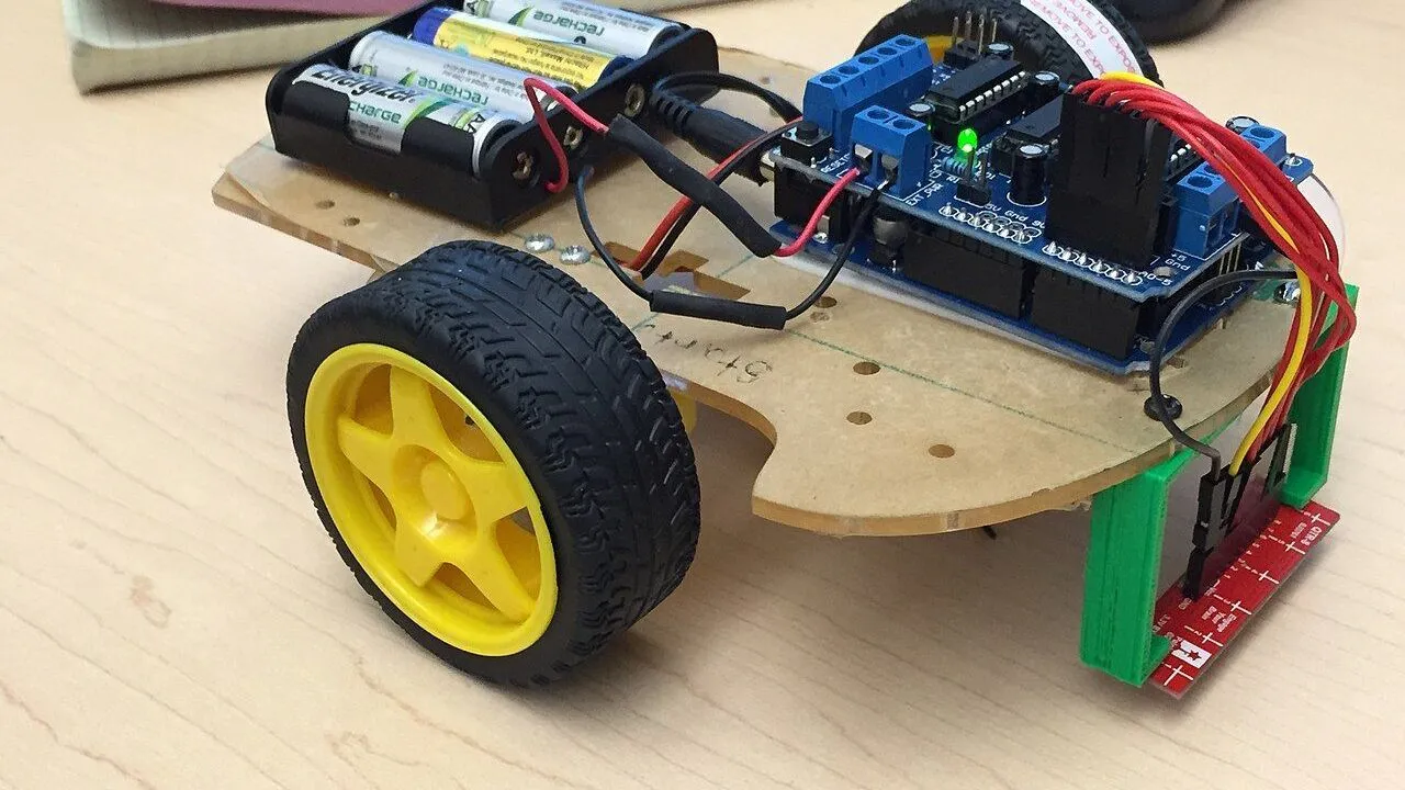
Your robot car drives its first square: straight ahead, a quarter turn to the right, four times, and then it stops. You will learn how the Uno controls two motors through the L298N motor driver, how PWM sets the speed, and why a robot that only counts time never drives a perfect square. It is a beginner project and takes about 45 minutes.
What you need
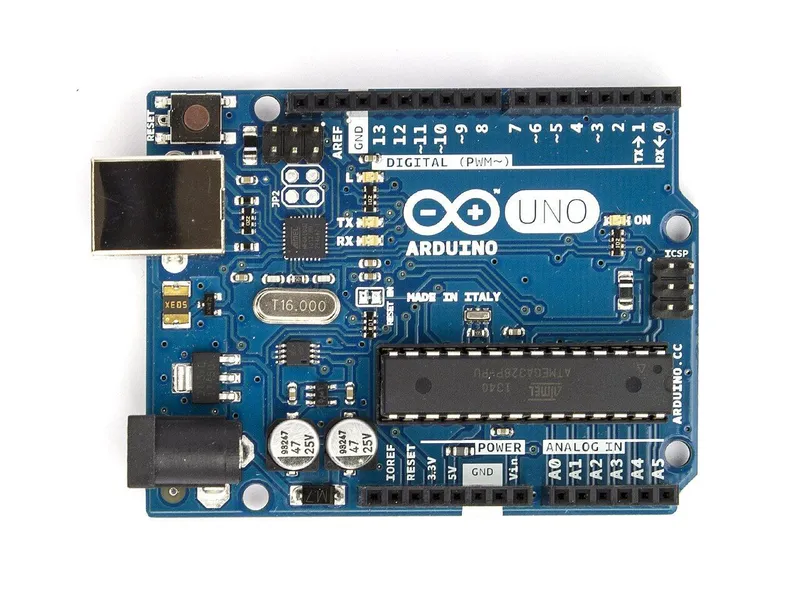 Arduino Uno R3In the simulator× 1See the price in the shop
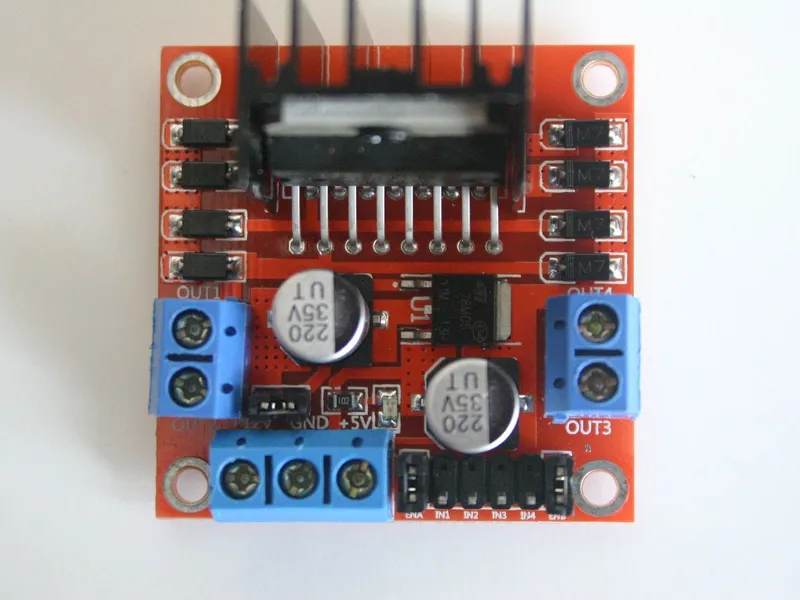 L298N motor driver moduleIn the simulator× 1See the price in the shop
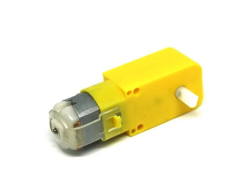 TT gear motor 1:48 with 65 mm wheelIn the simulator× 2See the price in the shop
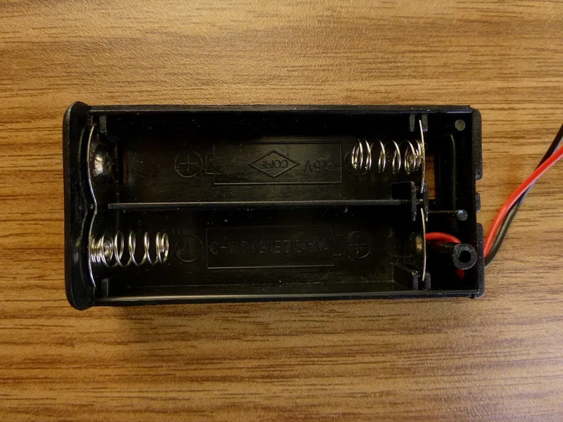 4 × AA battery holderIn the simulator× 1See the price in the shop
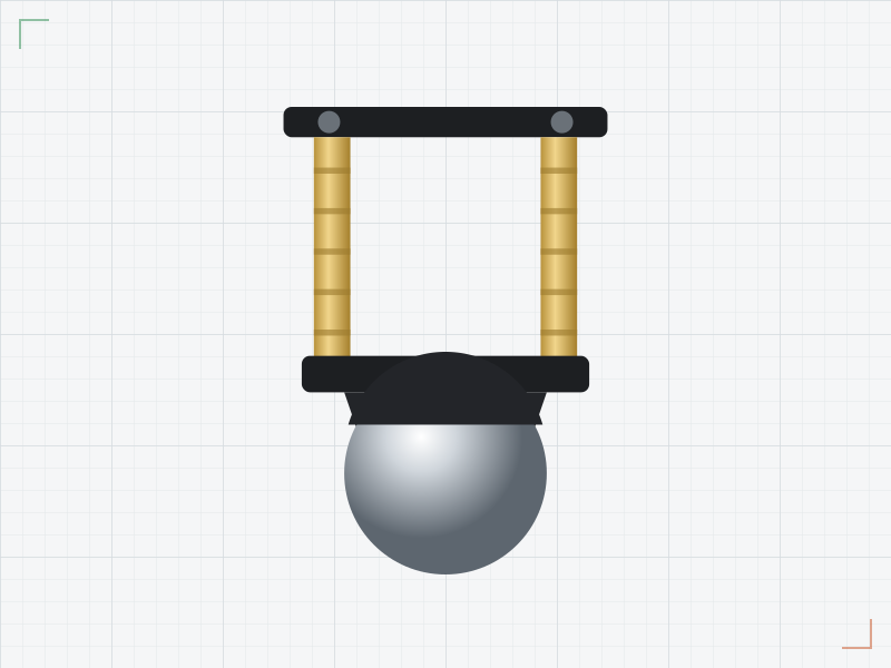 Ball caster 20 mmIn the simulator× 1See the price in the shop
 Jumper wire set× 1See the price in the shop
 USB A–B cable for Arduino Uno× 1See the price in the shop
You also need four AA batteries and a small screwdriver for the L298N's screw terminals. The Market has the car as a robot car kit.
How it works
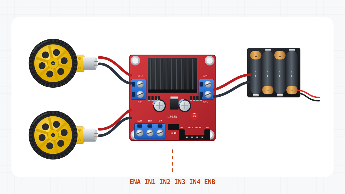
The motor driver
An Uno pin can give about 20 mA safely. A TT gear motor needs about 0.3 A while it drives, and up to about 1 A when it is blocked. So the Uno only sends signals. The L298N motor driver switches the battery's current to the motors.
The L298N has two H-bridges, one for each motor. An H-bridge can connect the motor to the battery either way round, so the motor turns forwards or backwards. The left motor is controlled by ENA, IN1 and IN2:
| ENA | IN1 | IN2 | The motor |
|---|---|---|---|
| HIGH or PWM | HIGH | LOW | turns forwards |
| HIGH or PWM | LOW | HIGH | turns backwards |
| HIGH | HIGH | HIGH | brakes |
| HIGH | LOW | LOW | brakes |
| LOW | any | any | coasts: it turns freely |
The right motor works the same way with ENB, IN3 and IN4.
PWM: how the speed is set
A pin can only be HIGH or LOW. For a lower speed, analogWrite() switches the pin that drives ENA on and off very fast, about 980 times per second on D5 and D6. The number from 0 to 255 sets how much of each cycle is on. With 200, the motor gets power 200/255 of the time, about 78%, so it turns more slowly. This is PWM, pulse-width modulation.
Power
Four AA cells give about 6 V to the L298N's +12V terminal. The label says +12V, but the module works from 6 V. The L298N loses about 1.8 V inside, so at full speed the motors get about 4.2 V.
The L298N also has a small 5 V regulator. Its +5V terminal powers the Uno through the Uno's 5V pin. From four AA cells it gives about 4.4 V: enough, but a little low. A GND wire joins the two boards. Signals only work when both boards share the same 0 V, which is called a common ground.
Steering with two wheels
The car steers with the speeds of its two wheels. When both turn forwards, it drives straight. When the left wheel turns forwards and the right one backwards, it spins right on the spot. The ball caster only rolls along.
Both motors are the same, but the right one is mounted mirrored. With the same wiring, a "forward" signal would turn it backwards. That is why its leads go to OUT4 and OUT3, swapped on purpose.
Why the square is never perfect
The sketch measures nothing. It says "spin for 450 ms" and hopes that this makes a quarter turn. Control without measuring is called open-loop control. The real turn depends on:
- The batteries. New AA cells give about 1.5 V each, about 6 V together. Nearly empty ones give about 1.2 V each, about 4.8 V together. After the 1.8 V lost in the L298N, the motors get about 3 V instead of 4.2 V, and every turn gets shorter.
- The floor. Wheels slip on smooth tiles, and the ball caster drags on carpet.
- The motors. No two TT motors are exactly the same. If one turns a little faster, the car curves on the straight sides.
- Momentum. The car does not stop at once when the sketch changes from driving to turning. It slides a little further.
So TURN_MS gives a good square only with the floor and the batteries you tuned it on. To be exact, a robot must measure what really happened. That is what sensors do, and the next projects add them.
Build it
1. Get the car in the simulator
Obstacle avoider, the car that comes with the game, has this car's decks, motors, wheels, battery holder, Uno and L298N. It also has an HC-SR04, which this project does not use: take it off in Build, or leave it, because the sketch never reads it. Its wires are not the ones in the table below, so you redo them in step 2.
Real build: screw the two TT motors under the lower deck, push on the 65 mm wheels and fix the ball caster under the front. Put the battery holder between the two decks. On the upper deck, mount the Uno at the back and the L298N in front of it. Leave the batteries out for now.
2. Wire the car
| From | To | Why |
|---|---|---|
| Battery + | L298N +12V | Motor power: about 6 V from four AA cells |
| Battery - | L298N GND | The battery’s minus |
| L298N +5V | Uno 5V | The driver’s regulator powers the Uno: about 4.4 V |
| L298N GND | Uno GND | Common ground: the signals need the same 0 V |
| Uno D5 | L298N ENA | Left motor speed (PWM); the ENA jumper is removed |
| Uno D4 | L298N IN1 | Left motor direction |
| Uno D7 | L298N IN2 | Left motor direction |
| Uno D8 | L298N IN3 | Right motor direction |
| Uno D12 | L298N IN4 | Right motor direction |
| Uno D6 | L298N ENB | Right motor speed (PWM); the ENB jumper is removed |
| Left motor M+ | L298N OUT1 | |
| Left motor M- | L298N OUT2 | |
| Right motor M+ | L298N OUT4 | Swapped on purpose: this motor is mounted mirrored |
| Right motor M- | L298N OUT3 | Swapped on purpose: this motor is mounted mirrored |
The simulator checks the wiring and shows problems, for example a missing common ground, or the L298N's 5 V on VIN instead of 5V.
Real build: pull the two small jumpers off ENA and ENB before you connect D5 and D6. With the jumpers on, the motors always run at full speed. Most modules have one more jumper next to the power terminals. Leave that one on: it switches on the 5 V regulator. Pull each wire in a screw terminal gently to check that it holds.
3. Upload the sketch
Open Code, paste the FirstDrive sketch from this page, press Verify, then Upload.
Real build: put the batteries in and set the car on a box, so that the wheels hang in the air. Connect the USB cable and upload. When the wheels start, check them. On the straight sides, both wheels turn forwards. In the turns, the left wheel turns forwards and the right wheel backwards.
4. Drive the square
Start a run in an arena. After one second, the car drives the square once and stops. The live readout shows the motors and the battery.
Real build: unplug the USB cable. Put the car on a flat floor with about a metre of free space each way, and press the RESET button on the Uno. One second later, the car drives the square. Press RESET again to repeat it.
5. Tune the turn
Watch the first corner. Did the car turn a quarter turn (90 degrees), or more, or less?
| What you see | What to change |
|---|---|
| The turn is too small | raise TURN_MS by 20 to 30 |
| The turn is too big | lower TURN_MS by 20 to 30 |
| The turns are different every time | lower SPEED, for example to 160, then tune TURN_MS again |
| The sides are too long or too short | change STRAIGHT_MS |
Change one number at a time, then upload and test again. A slower spin needs a longer TURN_MS. Keep SPEED above about 90, because below that, TT motors may only hum. Then try your numbers on the real car, and later with older batteries. The square changes, although the sketch stays the same.
The code
// First drive: the robot drives a square once, then stops.
// L298N: ENA -> D5, IN1 -> D4, IN2 -> D7 (left motor, A)
//        ENB -> D6, IN3 -> D8, IN4 -> D12 (right motor, B)
// The ENA and ENB jumpers are off: the Arduino sets each motor's speed with PWM.

const byte ENA = 5, IN1 = 4, IN2 = 7;
const byte ENB = 6, IN3 = 8, IN4 = 12;

const int SPEED = 200;           // 0..255
const int STRAIGHT_MS = 1200;    // one side of the square
const int TURN_MS = 450;         // about a quarter turn: tune it for your robot and floor

// speed from -255 (full backwards) to 255 (full forwards); 0 lets the motor coast
void setMotor(byte enablePin, byte inA, byte inB, int speed) {
  speed = constrain(speed, -255, 255);
  digitalWrite(inA, speed > 0);
  digitalWrite(inB, speed < 0);
  analogWrite(enablePin, abs(speed));
}

void drive(int left, int right) {
  setMotor(ENA, IN1, IN2, left);
  setMotor(ENB, IN3, IN4, right);
}

void setup() {
  const byte pins[] = {ENA, IN1, IN2, ENB, IN3, IN4};
  for (byte pin : pins) pinMode(pin, OUTPUT);

  delay(1000);                   // one second to put the robot down
  for (int side = 0; side < 4; side++) {
    drive(SPEED, SPEED);         // straight ahead
    delay(STRAIGHT_MS);
    drive(SPEED, -SPEED);        // spin right on the spot
    delay(TURN_MS);
  }
  drive(0, 0);                   // done: stop
}

void loop() {
  // Nothing here: the square is driven once, in setup().
}Pins and settings
The first lines name the six driver pins, as in the wiring table. Below them are the three settings that you tune: SPEED, STRAIGHT_MS and TURN_MS.
setMotor(): one motor
void setMotor(byte enablePin, byte inA, byte inB, int speed) {
  speed = constrain(speed, -255, 255);
  digitalWrite(inA, speed > 0);
  digitalWrite(inB, speed < 0);
  analogWrite(enablePin, abs(speed));
}
The speed goes from -255 (full speed backwards) to 255 (full speed forwards), and constrain() keeps it in that range. For a forward speed, speed > 0 is true, and true means HIGH. So inA goes HIGH and inB goes LOW: "forwards" in the driver table. A backward speed does the opposite. For 0, the enable pin is LOW too, so the motor coasts. analogWrite() sets the PWM from the speed without its sign: abs(-200) is 200.
drive(): both motors
drive(left, right) calls setMotor() twice: for the left motor on ENA, IN1 and IN2, and for the right motor on ENB, IN3 and IN4. From here on, the sketch thinks only in wheel speeds.
setup(): the whole square
First, the six control pins become outputs: for (byte pin : pins) calls pinMode() for each pin in the array. Then comes the square:
  delay(1000);                   // one second to put the robot down
  for (int side = 0; side < 4; side++) {
    drive(SPEED, SPEED);         // straight ahead
    delay(STRAIGHT_MS);
    drive(SPEED, -SPEED);        // spin right on the spot
    delay(TURN_MS);
  }
  drive(0, 0);                   // done: stop
The for loop runs its body four times, once for each side. drive() sets the motors, and delay() lets them run. The pins keep their setting until the sketch changes them. At the end, drive(0, 0) stops both motors. loop() is empty, so the square runs only once. Press RESET to drive it again.
If it does not work
- A wheel turns the wrong way, or the car spins instead of driving straight. Swap that motor's two leads on the L298N: OUT1 with OUT2, or OUT3 with OUT4. Test with the wheels in the air, as in step 3.
- Nothing moves. Check the batteries, the wires to +12V and GND, and the GND wire between the L298N and the Uno. In the simulator, read the problems that the wiring check shows.
- The motors always run at full speed (real build). The jumpers on ENA and ENB are still on.
- One motor does not turn. Check its enable wire (D5 to ENA, D6 to ENB) and its leads.
- The Uno does not start from the batteries. The L298N's +5V must go to the Uno's 5V pin, not to VIN. VIN needs 7-12 V, so 4.4 V there is too low.
- The car starts the square, stops, and starts again. The Uno resets. Starting motors pull the battery voltage down, and the Uno's supply drops too. This is called a brown-out. Use new batteries and short power wires. Add a 100-470 µF capacitor across +12V and GND near the driver, with its - leg on GND. See why robots reset.
Next steps
Driving by time has a limit: the robot cannot see what it did. The next project gives the car an ultrasonic sensor, so it can see a wall and react: the obstacle-avoiding robot.
To learn more, read the lesson on motors and the L298N, and the articles on TT gear motors and which motor driver to choose. If you are new to robots, start with the lesson on what a robot is.
Make it better
- Drive a triangle: three sides and three turns of 120 degrees. Find the new turn time.
- Drive the square to the left: move the minus sign in the turn to the other wheel.
- If the car curves on the straight sides, give the faster motor a slightly lower speed.