L298N, L9110S or TB6612: which motor driver?
Four common motor drivers compared: supply voltage, current, the volts each one wastes, pins per motor and how each one stops. Which one suits a small robot with TT motors, and why.
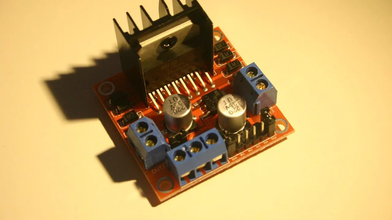
Photo: Les Pounder · CC BY-SA 2.0
An Arduino pin can give about 20 mA safely. A TT gear motor takes about 0.3 A while it drives and up to about 1 A when it is stalled. So a motor driver sits in between: the battery's current flows through the driver to the motor, and the Arduino only tells the driver what to do.
Four drivers are common in small robots: the L298N, the L9110S, the MX1508 and the TB6612FNG (often just called TB6612). They do the same job in different ways, and the differences show up in speed, battery life and code.
Inside every driver: an H-bridge
Each board has two H-bridges, one per motor. An H-bridge is four electronic switches around the motor. Drawn on paper, it looks like the letter H, with the motor as the bar in the middle. One diagonal pair of switches on: the motor turns forwards. The other pair: it turns backwards. Both bottom switches on, or both top ones: the motor's two leads are joined, and a turning motor brakes quickly. All four off: the motor coasts to a stop.
The drivers differ in what their switches are made of, and in which pins control them.
The four drivers side by side
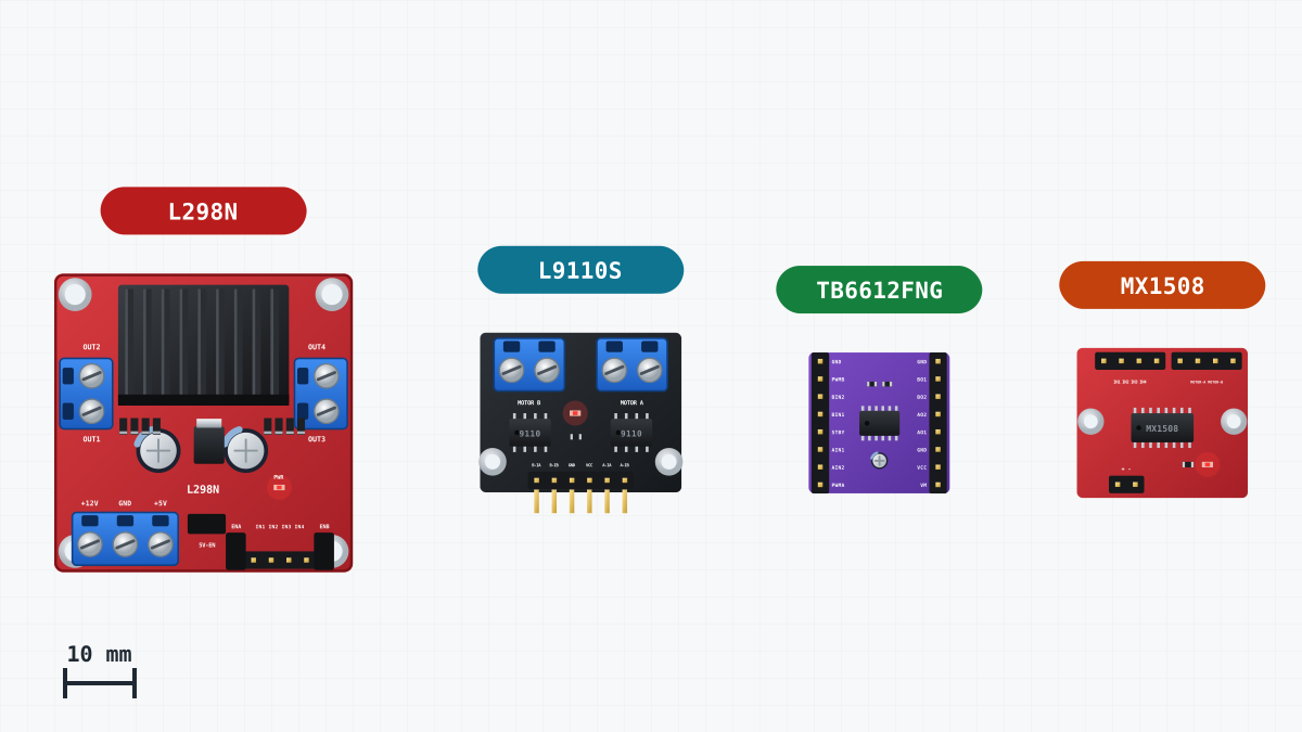
| Driver | Motor voltage | Current per motor | Voltage lost inside | Pins per motor | Equal inputs |
|---|---|---|---|---|---|
| L298N | 5-35 V | up to 2 A (about 1 A without extra cooling) | about 1.8-2 V | 3: ENA, IN1, IN2 | brake, while ENA is HIGH |
| L9110S | 2.5-12 V | about 0.8 A | about 1.85 V at 0.75 A | 2 | both LOW or both HIGH: stop |
| MX1508 | 2-9.6 V | about 1.5 A | small | 2 | both LOW: coast; both HIGH: brake |
| TB6612FNG | 4.5-13.5 V | 1.2 A | very little | 3: PWMA, AIN1, AIN2, plus STBY | both LOW: coast; both HIGH: brake |
Motor B of the L298N uses ENB, IN3 and IN4. On the L298N, ENA LOW lets the motor coast, whatever IN1 and IN2 say.
Bipolar or MOSFET: where the volts go
The L298N uses bipolar transistors as its switches. A bipolar transistor that is fully on still keeps about a volt across itself. The motor's current always passes through two switches: one on the battery's + side and one on the GND side. Together they lose about 1.8-2 V, and more as the current grows.
On the CoreEngine robot car, four AA cells give about 6 V. About 1.8 V stays inside the L298N, so the motors get about 4.2 V. The lost part turns into heat in the chip. That is why the module carries a large metal heat sink.
A MOSFET works differently. When it is fully on, it behaves like a small resistor, so the voltage lost is simply current × resistance. At the currents of TT motors, that is a fraction of a volt. The TB6612FNG's datasheet gives about 0.15 V for the two switches together at 0.3 A. The MX1508 uses MOSFETs too. With these drivers, the motors get almost the whole battery voltage.
The loss matters most at low voltage. Two volts lost from a 12 V supply is a sixth of it. Two volts lost from four AA cells is a third. Small robots run on low voltage, so this is where a MOSFET driver helps most. The small L9110S does not help here: its datasheet shows about 1.85 V lost at 0.75 A.
Two-pin drivers: equal inputs differ
The L9110S and the MX1508 have no enable pin. Each motor has two inputs, and the pair sets both the direction and the speed. For speed, you hold one input steady and send PWM to the other.
The two chips do not agree about equal inputs:
| Inputs | MX1508 | L9110S |
|---|---|---|
| both LOW | outputs off: the motor coasts | both outputs LOW: the motor stops |
| both HIGH | brake | both outputs LOW: the motor stops |
PWM switches an input on and off hundreds of times a second. With the other input held LOW, every "off" moment makes the two inputs equal. In those moments the MX1508 lets the motor coast, and the L9110S stops it. So the same speed value can give a different speed, and a robot that rolls to a gentle stop with one driver stops sharply with the other. Code written for one board is not automatically right for the other. Read the truth table of the exact board you buy.
Which one for a small robot with TT motors?
Choose by the stall current, not by the driving current. Every start begins as a short stall of up to about 1 A, and a robot that pushes against a wall stays stalled.
- L9110S: small and simple. Its 0.8 A is enough for driving, but a stalled TT motor can ask for more.
- MX1508: small, and it works from four AA cells. Its 1.5 A covers a stall, and it loses little. Its speed code is written for two pins.
- TB6612FNG: the best fit for this job. It loses very little, its 1.2 A covers a stall, and it is controlled like the L298N: one PWM pin and two direction pins per motor. Its STBY pin must be HIGH, or the outputs stay off.
- L298N: large, and the motors get about 1.8 V less. But it is robust, common and simple to wire.
For a new robot on four AA cells, a MOSFET driver such as the TB6612FNG passes the most of the battery's voltage to the motors. The L298N is the safe and common choice, and it is the one this site uses.
Why the CoreEngine robot car uses the L298N
- It is common and robust. Many robot car kits include it. Up to 2 A per channel is far more than TT motors need while driving, and it has a heat sink and screw terminals.
- It powers the Uno. Its own 5 V regulator feeds the Uno's 5V pin (about 4.4 V from four AA cells, which is enough), so one battery holder runs the whole robot.
- Its code is easy to read. Speed goes to ENA and ENB, direction to IN1 to IN4.
- It is in the simulator, with its voltage loss built in, so you can test every project on this site there first.
The lesson Motors and the L298N driver explains its pins, and the Market has the module.
Switching drivers later
All the site's sketches control the driver through one small function:
// speed from -255 (full backwards) to 255 (full forwards); 0 lets the motor coast
void setMotor(byte enablePin, byte inA, byte inB, int speed) {
  speed = constrain(speed, -255, 255);
  digitalWrite(inA, speed > 0);
  digitalWrite(inB, speed < 0);
  analogWrite(enablePin, abs(speed));
}
Everything else, such as drive(), the state machine and the timers, only calls this function.
Moving to a TB6612FNG. PWMA, AIN1 and AIN2 take the places of ENA, IN1 and IN2. PWMB, BIN1 and BIN2 take those of ENB, IN3 and IN4. The motors go on the A and B outputs, with the right motor's leads swapped as before. STBY and VCC (its logic supply) go to the Uno's 5V, VM to the battery's +, and all GNDs are joined. setMotor() works unchanged. Three things change:
- The motors get more voltage, so the same speed value is faster. Tune times such as the turn in First drive again.
- Between PWM pulses, the TB6612FNG brakes, where the L298N lets the motor coast.
- It has no 5 V regulator, so the Uno needs its own supply, for example a USB power bank in its USB socket.
Moving to an MX1508 or L9110S. Here setMotor() must change, because there is no enable pin. Each motor needs PWM on one of its two inputs, so check which PWM pins are still free. Neither board has a 5 V regulator.
Whatever driver you choose, join its GND to the Uno's GND: the signals only make sense against a common ground. To see what the motors themselves need, read TT gear motors: what the numbers mean.