TT gear motors: what the numbers mean
Ratio, rpm, torque, current and voltage of the TT gear motor explained with real numbers: robot speed, stall current, why two motors differ and why low PWM does not start them.
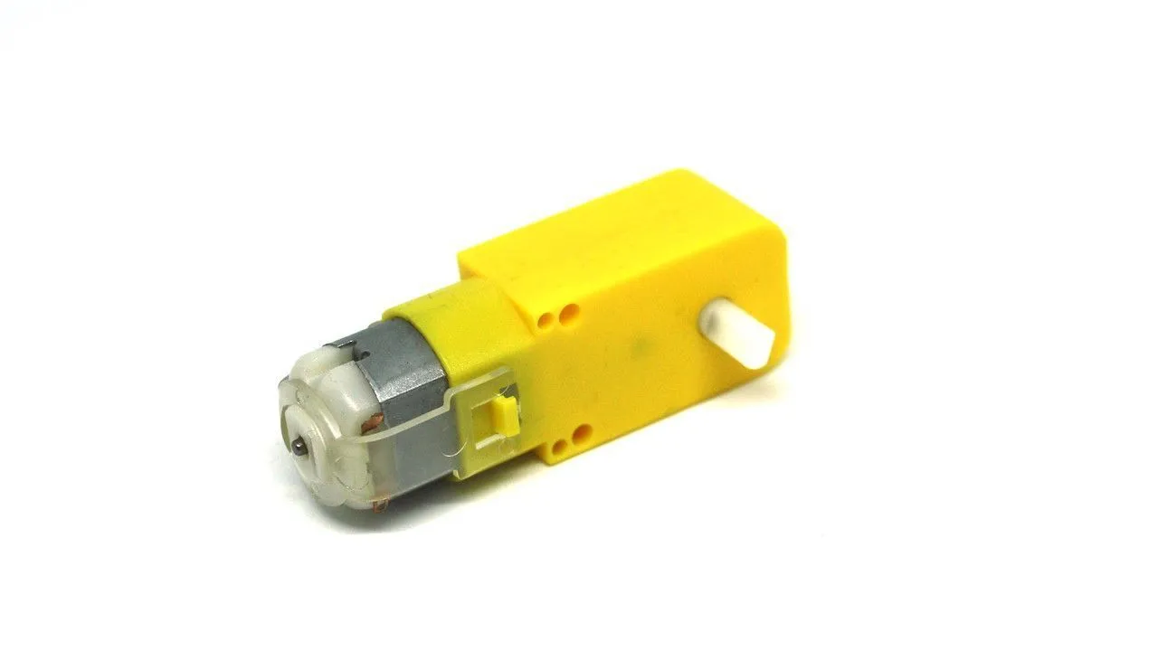
Photo: Lukas Ruge · CC0
The TT gear motor is the small DC motor with a plastic gearbox, usually yellow, that drives many beginner robot cars. The CoreEngine robot car uses two of them, with 65 mm wheels. Its numbers look simple, but each one tells you something about your robot.
The ratio 1:48 trades speed for force
Inside the box is a small motor that spins very fast, and a gearbox that slows it down. The ratio 1:48 means that the motor turns 48 times for one turn of the output shaft. To give 200 rpm at the wheel, the motor inside spins at about 9,600 rpm.
A gearbox trades speed for torque. Without friction, 48 times slower would mean 48 times more torque. Plastic gears lose part of that, but the wheel still gets far more turning force than the bare motor could give. TT motors are also sold with other ratios. A higher ratio gives a slower, stronger wheel.
From rpm to robot speed
Without load, at 6 V, a TT motor turns at about 200-250 rpm (turns per minute). The robot's speed follows from the wheel: speed = rpm × π × wheel diameter. Here is a worked example with a 65 mm wheel at about 200 rpm:
| Step | Calculation | Result |
|---|---|---|
| Distance for one wheel turn | π × 65 mm | about 204 mm |
| Wheel turns per second | 200 / 60 | about 3.33 |
| Speed | 3.33 × 0.204 m | about 0.68 m/s |
That is the top speed with the wheel in the air at 6 V. The real robot is slower. On the CoreEngine robot car, the motors get about 4.2 V through the L298N, and the speed without load is roughly proportional to the voltage. So expect roughly two thirds of it, and a little less again with the robot's weight on the wheels.
Torque: turning force
Torque is how hard the shaft can turn. At the wheel, it becomes a push against the floor: push = torque / wheel radius. So with the same motor, a wheel twice as big drives twice as fast but pushes only half as hard.
Torque and current go together. The harder the motor must push, for example on a ramp, on a carpet or with a heavier robot, the more current it takes. The most torque comes when the motor is stalled, and so does the most current. Shops quote very different torque figures for TT motors, so do not rely on one number. Test your robot on the floor where it will drive.
Current: idle, driving, stalled
| One TT motor | Current |
|---|---|
| Turning freely, no load | about 0.1-0.15 A |
| Driving the robot | about 0.3 A |
| Stalled: not turning, full voltage | up to about 1 A |
The stall current is the number that matters most:
- Every start is a short stall. For a moment, before the motor turns, it takes stall current. Two motors starting together can ask for up to about 2 A.
- The driver must handle it. The L298N is rated up to 2 A per channel and the TB6612FNG 1.2 A. The L9110S, at about 0.8 A per channel, is below the stall current of a TT motor. See L298N, L9110S or TB6612: which motor driver?
- The battery dips under it. Two stalled motors pull the battery's voltage down, and the Arduino can reset. See Why your robot resets.
A stalled motor turns all its power into heat. If a wheel is blocked, or the motor hums without turning, stop it.
Voltage range
A TT motor is made for 3-6 V and can run on up to about 8 V. More voltage means more speed and more current. Above 6 V it runs hotter, and it wears out sooner. On the CoreEngine robot car, about 4.2 V reaches the motors, well inside the range. With two Li-ion cells (about 7.4 V), the motors would get about 5.6 V after the L298N's loss.
Why two "identical" motors differ
Two motors from the same box never match exactly. Their magnets, windings, brushes and gear friction differ a little. A motor can even run a little faster in one direction than in the other. The robot adds its own differences: a wheel pressed on at a slight angle, a caster that pulls to one side, more weight on one side. The result: with the same speed value on both motors, the robot drives in a curve.
To compensate:
- Drive straight ahead for a few seconds on a smooth floor. If the robot curves to the left, its right wheel is faster.
- Slow the faster motor a little in code, then test again. For example:
const int RIGHT_PERCENT = 95;   // this robot curves left: its right motor is a little faster

void driveStraight(int speed) {
  drive(speed, speed * RIGHT_PERCENT / 100);
}- Call
driveStraight(SPEED)where First drive callsdrive(SPEED, SPEED). Check the value again when the batteries get older or the speed changes, because the difference is not the same at every speed.
For truly straight driving, robots use wheel encoders: sensors that count wheel turns, so that the code can match the counts. It is the same feedback idea as the P controller in the Keep-distance robot.
Electrical noise and the small capacitor
Inside the motor, small brushes slide over a turning contact, the commutator. Each time they move from one contact to the next, the current switches, and tiny sparks form. These sparks send electrical noise down the motor wires. The noise can disturb the Arduino and the sensors: you get odd readings, or even resets.
The usual cure is a small ceramic capacitor of about 0.1 µF (100 nF, often marked "104"), soldered straight across the motor's two terminals. It has no polarity, so either way round is fine. Also keep the motor wires short, twist the two wires of each motor together, and keep them away from sensor wires.
The dead band: low PWM does not start the motor
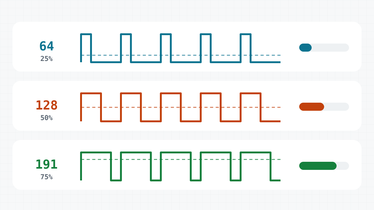
analogWrite(ENA, value) sets the share of time the motor gets power, from 0 to 255. With a small value, the average voltage is too low to overcome the friction in the gearbox and the brushes. The motor hums but does not turn. This range of low values is the dead band. The hum itself is the PWM: about 980 Hz on D5 and D6.
A motor also needs more to start than to keep turning. Once it moves, it may keep going at a value that could not start it. The dead band grows when the batteries are low, and when the robot is heavy or stands on a carpet.
Code can step over the dead band. The Keep-distance robot never asks for less than a minimum speed:
const int MIN_SPEED = 90;      // below this the motors only hum and do not turn

// in loop(), after the controller has computed the speed:
if (abs(speed) < MIN_SPEED) speed = (speed > 0) ? MIN_SPEED : -MIN_SPEED;
To find the value for your robot, raise the speed slowly in small steps and print each value to the Serial Monitor. Note where the wheels start to turn. The MotorTest sketch in the lesson Motors and the L298N driver ramps from 0 to 255 in steps of 5, so it is a good place to start. The Market has the motors.