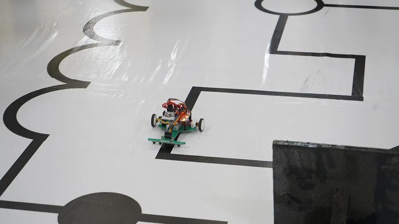
A line-following robot drives along a black line on a white floor, around curves, by itself. Two infrared line sensors under the front of the car look at the floor, one on each side of the line. When the line moves under one sensor, the robot turns toward that side. You will learn how an IR sensor tells black from white, how its comparator makes a clean HIGH or LOW signal, and how four simple cases steer the robot. It is a medium project and takes about 90 minutes.
What you need
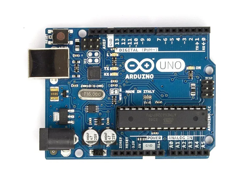 Arduino Uno R3In the simulator× 1See the price in the shop
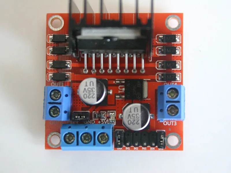 L298N motor driver moduleIn the simulator× 1See the price in the shop
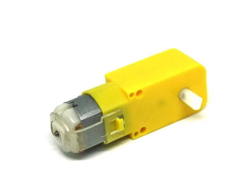 TT gear motor 1:48 with 65 mm wheelIn the simulator× 2See the price in the shop
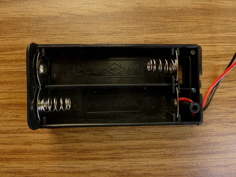 4 × AA battery holderIn the simulator× 1See the price in the shop
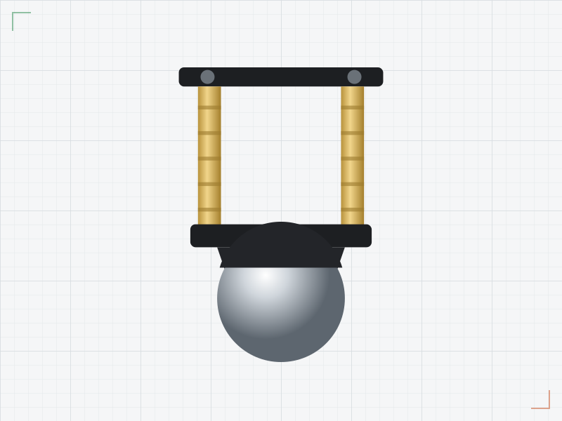 Ball caster 20 mmIn the simulator× 1See the price in the shop
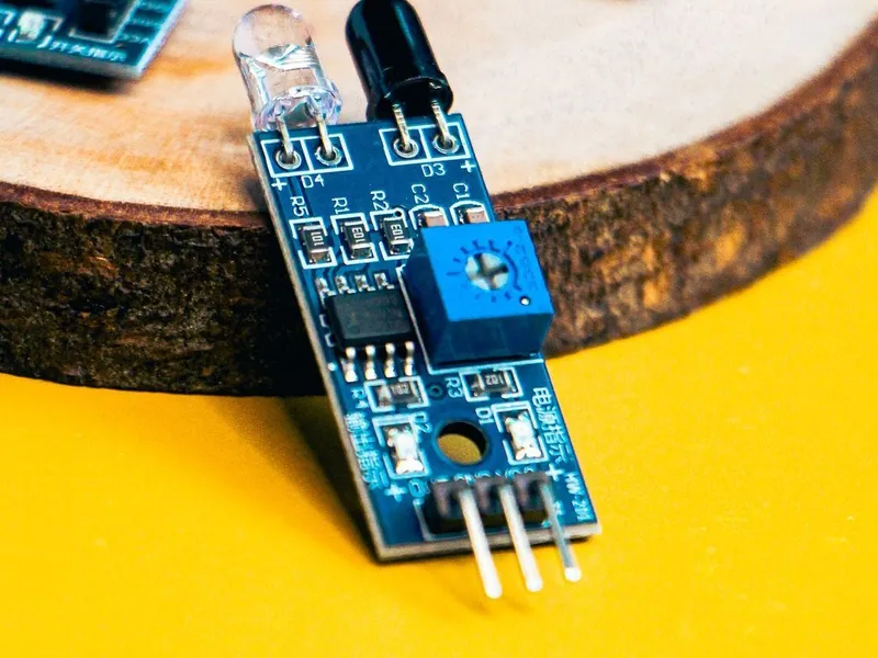 IR line sensor moduleIn the simulator× 2See the price in the shop
 Jumper wire set× 1See the price in the shop
This is the car from First drive, without the HC-SR04, plus two IR line sensor modules. See the line follower add-on in the Market. For the track, you need a white surface and black tape about 2 cm wide, such as black insulating tape. A large sheet of white card or a smooth, light floor works well. You also need a small screwdriver to adjust the sensors.
How it works
How the sensor sees the line
Each module has an infrared (IR) LED and an IR receiver side by side, both looking down. The LED shines infrared light at the floor. You cannot see this light, but the receiver can. A white floor reflects most of it back into the receiver. A black line absorbs most of it, so little light comes back.
The receiver turns the light into a voltage that depends on how much light comes back. A comparator chip on the module, often an LM393, compares this voltage with a threshold. The small potentiometer on the module sets that threshold. The result is a clean digital signal on the OUT pin:
| Under the sensor | IR light that comes back | OUT |
|---|---|---|
| White floor | a lot | LOW |
| Black line | little | HIGH |
Turning the potentiometer moves the point where OUT changes. That is how you adjust the sensor to your floor, your line and the height of the sensor. Most modules also have a small LED that shows the state of OUT, so you can adjust them without a computer.
Where the sensors go
The two sensors sit under the front of the car, about 5 mm above the floor (a TCRT5000 sees the floor from about 0.2 to 15 mm away), one on each side of the line. The gap between them is a little wider than the line. So when the robot is centred on the line, both sensors see white. Left and right mean the robot's own left and right, as you look at it from behind. The left sensor's OUT goes to D2, and the right sensor's OUT goes to D3.
The four cases
| Left (D2) | Right (D3) | What it means | Motors | The robot |
|---|---|---|---|---|
| LOW: white | LOW: white | the line is between the sensors | drive(170, 170) |
drives straight |
| HIGH: black | LOW: white | the line has moved to the left | drive(-70, 170) |
turns left |
| LOW: white | HIGH: black | the line has moved to the right | drive(170, -70) |
turns right |
| HIGH: black | HIGH: black | a cross line or the end of the track | drive(0, 0) |
stops |
Why turn toward the sensor that sees black? If the line is under the left sensor, the robot has drifted to the right of the line, or the line curves to the left. Turning left brings the line back between the sensors. In a turn, the outer wheel drives forwards at 170, and the inner wheel runs slowly backwards at 70. So the robot turns sharply.
loop() has no delay(). It reads both sensors thousands of times per second, so the robot reacts as soon as the line moves.
Build it
1. Start from the car
Start from Obstacle avoider, the car that comes with the game, or from your car from First drive. In Build, take off the HC-SR04 and add two IR line sensor modules; the next steps show where they go and how to wire them. Then paste the LineFollower sketch into Code and press Upload. On line track A, the robot starts on the line.
Real build: use your car from First drive. This robot does not need the HC-SR04.
2. Mount the sensors
Fix the two modules under the front of the car, with the sensors looking down, about 5 mm above the floor.
Real build: the lower deck is about 4 cm above the floor, so the modules need spacers or a small bracket to come down to about 5 mm. Make the gap between the two sensors a little wider than the line: for a 2 cm line, about 3-4 cm. On the simulator's car they are 3.6 cm apart, one on each side of the caster. If they are too close, both see black on straight parts. If they are too far apart, the robot wanders far from the line before a sensor sees it.
3. Wire the sensors
| From | To | Why |
|---|---|---|
| Battery + | L298N +12V | Motor power: about 6 V from four AA cells |
| Battery - | L298N GND | The battery’s minus |
| L298N +5V | Uno 5V | The driver’s regulator powers the Uno: about 4.4 V |
| L298N GND | Uno GND | Common ground: the signals need the same 0 V |
| Uno D5 | L298N ENA | Left motor speed (PWM); the ENA jumper is removed |
| Uno D4 | L298N IN1 | Left motor direction |
| Uno D7 | L298N IN2 | Left motor direction |
| Uno D8 | L298N IN3 | Right motor direction |
| Uno D12 | L298N IN4 | Right motor direction |
| Uno D6 | L298N ENB | Right motor speed (PWM); the ENB jumper is removed |
| Left motor M+ | L298N OUT1 | |
| Left motor M- | L298N OUT2 | |
| Right motor M+ | L298N OUT4 | Swapped on purpose: this motor is mounted mirrored |
| Right motor M- | L298N OUT3 | Swapped on purpose: this motor is mounted mirrored |
| Left line sensor VCC | L298N +5V | 5 V for the sensor |
| Left line sensor GND | Uno GND | Ground |
| Left line sensor OUT | Uno D2 | LOW over white, HIGH over the black line |
| Right line sensor VCC | Uno 3V3 | The +5V terminal already holds two wires; 3.3 V is enough for the module |
| Right line sensor GND | Uno GND | Ground |
| Right line sensor OUT | Uno D3 | Same as the left sensor |
Each module has three pins: VCC to 5 V (or 3.3 V), GND to GND, and OUT to the Uno. The left OUT goes to D2 and the right OUT to D3. The motor wiring stays as in First drive.
Real build: on some modules, OUT is marked DO. If your module also has an AO pin, leave it free, because this project uses only the digital output. The wiring table shows which 5 V and GND point each sensor uses: the L298N's +5V terminal already holds two wires, so the right sensor takes its power from the Uno's 3.3V pin. The module works from 3.3 V to 5 V.
4. Make a track
Stick black tape about 2 cm wide on a white surface. Start with a large oval, because gentle curves are easier than sharp corners. Press the tape down flat, without wrinkles or gaps. Where you want the robot to stop, add a short cross line.
5. Adjust the sensors
Real build: take the batteries out, so that the wheels cannot turn. Connect the USB cable: now the Uno and the sensors run from the computer. Stand the car on the track and adjust one sensor at a time:
- Put the sensor over the white floor and look at its LED.
- Move the car so that the sensor is over the black line. The LED must change.
- If it does not change, turn the potentiometer a little with the screwdriver and try again.
- Test a few places on the track, until the LED changes every time.
6. Upload and run
Upload the sketch. Then unplug the USB cable, put the batteries in while you hold the car, and set it down with the line between the two sensors. It starts at once. Watch the first curve. If the robot follows it, try a sharper one. If it leaves the line, see the tips below.
The code
// Line follower: two IR sensors look down at the floor, one each side of a black line.
// Each sensor's OUT is LOW over the white floor and HIGH over the black line.
// L298N: ENA -> D5, IN1 -> D4, IN2 -> D7 (left), ENB -> D6, IN3 -> D8, IN4 -> D12 (right)
// IR sensors: left OUT -> D2, right OUT -> D3

const byte ENA = 5, IN1 = 4, IN2 = 7;
const byte ENB = 6, IN3 = 8, IN4 = 12;
const byte LEFT_EYE = 2, RIGHT_EYE = 3;

const int FAST = 170;          // speed on a straight line
const int SLOW = 70;           // the inner wheel in a turn, driven backwards

void setMotor(byte enablePin, byte inA, byte inB, int speed) {
  speed = constrain(speed, -255, 255);
  digitalWrite(inA, speed > 0);
  digitalWrite(inB, speed < 0);
  analogWrite(enablePin, abs(speed));
}

void drive(int left, int right) {
  setMotor(ENA, IN1, IN2, left);
  setMotor(ENB, IN3, IN4, right);
}

void setup() {
  const byte pins[] = {ENA, IN1, IN2, ENB, IN3, IN4};
  for (byte pin : pins) pinMode(pin, OUTPUT);
  pinMode(LEFT_EYE, INPUT);
  pinMode(RIGHT_EYE, INPUT);
}

void loop() {
  bool leftOnLine = digitalRead(LEFT_EYE) == HIGH;
  bool rightOnLine = digitalRead(RIGHT_EYE) == HIGH;

  if (!leftOnLine && !rightOnLine) {
    drive(FAST, FAST);           // the line is between the sensors: straight on
  } else if (leftOnLine && !rightOnLine) {
    drive(-SLOW, FAST);          // the line went left: turn left
  } else if (!leftOnLine && rightOnLine) {
    drive(FAST, -SLOW);          // the line went right: turn right
  } else {
    drive(0, 0);                 // both see black: a cross line or the end, stop
  }
}Pins and speeds
const byte LEFT_EYE = 2, RIGHT_EYE = 3;

const int FAST = 170;          // speed on a straight line
const int SLOW = 70;           // the inner wheel in a turn, driven backwards
The sketch calls the sensors "eyes". FAST is the speed on a straight line. SLOW is the speed of the inner wheel in a turn, which runs backwards.
setup()
The six motor pins become outputs, as in every car sketch. The two sensor pins become inputs with pinMode(LEFT_EYE, INPUT) and pinMode(RIGHT_EYE, INPUT). The modules set OUT HIGH or LOW themselves, so no pull-up resistor is needed.
Reading the sensors
  bool leftOnLine = digitalRead(LEFT_EYE) == HIGH;
  bool rightOnLine = digitalRead(RIGHT_EYE) == HIGH;
digitalRead() gives HIGH or LOW. Comparing it with HIGH gives a bool: true or false. So leftOnLine is true when the left sensor sees black. Good names like these make the rest of loop() easy to read.
The four cases
  if (!leftOnLine && !rightOnLine) {
    drive(FAST, FAST);           // the line is between the sensors: straight on
  } else if (leftOnLine && !rightOnLine) {
    drive(-SLOW, FAST);          // the line went left: turn left
  } else if (!leftOnLine && rightOnLine) {
    drive(FAST, -SLOW);          // the line went right: turn right
  } else {
    drive(0, 0);                 // both see black: a cross line or the end, stop
  }
! means "not", and && means "and". The four branches match the four rows of the table above. The last one, else, catches the only case that is left: both sensors on black. setMotor() and drive() are the same as in First drive: a positive speed turns a wheel forwards, and a negative speed turns it backwards.
If it does not work
- The robot drives straight over the line. The sensors do not see it. Check that each module's LED changes between white and black, and adjust the potentiometer. Check the height (about 5 mm, never more than 1 cm), and check that OUT goes to D2 and D3.
- It turns away from the line instead of toward it. The left and right sensors are swapped. Swap the two OUT wires on D2 and D3.
- It stops all the time. Both sensors see "black". They may be too close together for your line, or too high above the floor: from too high, too little light comes back, and that looks like black. Or the threshold is set so that white also reads as black. Adjust the potentiometers again.
- It leaves the line in sharp curves. It is too fast to react. Lower FAST, or raise SLOW so that it turns harder.
- It zigzags a lot on straight parts. The turns are too hard. Lower SLOW a little, or lower FAST.
- It works in one room but not in another. Sunlight and some lamps contain infrared light that can blind the sensors. Test away from direct sunlight, and adjust the potentiometers again on each new floor.
- A sensor does not see your black line. Some black tapes and inks reflect infrared light, even though they look black to us. Shiny tape can also reflect the light straight back. Try a matte black tape, or a line printed on paper with a laser printer.
- A wheel turns the wrong way, or the robot resets. See the tips in First drive and why robots reset.
Next steps
Give the robot a second job: put the HC-SR04 back on and stop when something blocks the line. The line sensors use D2 and D3, and the HC-SR04 uses D9 and D10, so the pins do not clash. The obstacle-avoiding robot shows how to measure without stopping loop(). The lesson on millis() and states helps you combine several jobs in one sketch.
This robot only knows "on the line" or "off the line". Sensors with an analog output, read with analogRead(), can also tell how far the robot is from the line. Then a P controller, like the one in the keep-distance robot, can steer smoothly.
Make it better
- Find the highest FAST at which the robot still follows your track, then try a different SLOW.
- Light the Uno's L LED on D13 whenever the robot is turning.
- At a cross line, wait two seconds, then drive across it and follow the line again.